


Inputs and Outputs
3-16
Details
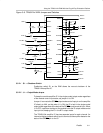
3.3.6 Inputs and Outputs
The TI plug-n-play audio amplifier evaluation platform is equipped with several
standard conectors for audio inputs and outputs.
3.3.6.1 Inputs
In most cases, audio signals enter the platform through either a pair of RCA
phono jacks (J3 and J5) or a miniature (1/8 inch) stereo phone jack (J4).
Certain signal conditioning and amplifier EVMs, however, may have additional
signal input connectors mounted on the module circuit board. The TPA6011A4
EVM has a special PC BEEP signal input pin (TP2) on the top of the module
PCB.
The platform audio signal input jacks (J3, J4, and J5) are of the closed-circuit
type, grounding the signal input lines when no plugs are inserted.
3.3.6.2 Outputs
Amplified audio output signals leave the platform through left and right RCA
phono jacks (J7 and J9), left and right pairs of compression connectors for
stripped speaker wires (J8), and optionally, through a miniature (1/8 inch)
stereo phone jack (J10), for headphones.
The audio output lines from the power amplifiers are separate all the way to
the edge of the platform (output jacks J7, J8, and J9). The OUT– lines from the
power amplifier sockets are not tied to each other or to platform ground. This
allows the TPA6011A4 power amplifier EVM to operate in the highly-efficient
bridge-tied load configuration when driving speakers.
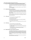
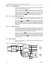
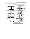
The headphone jack (J10) is capacitively coupled to source select switch S3,
which connects J10 to the output lines of either the headphone amplifier
socket or the power amplifier sockets (see Figure 3–6). When the TPA6011A4
output signal is routed to J10 by S3, signals output via J10 are returned to
platform ground when a plug is inserted (see Figure 3–8), requiring
single-ended operation of the power amplifiers.
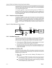
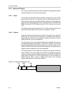
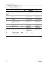
Figure 3–9. Typical Headphone Plug
Left Right GND