


Quick Start List for Stand-Alone
2-6
Quick Start
can be used with a differential or single-ended audio source, but the
headphone and line have common positive inputs.
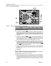
5) Select output mode:
a) For BTL output, connect a speaker to the module OUT+ and OUT–
pins of each channel,
or
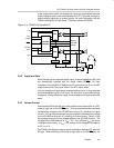
b) For single-ended output, connect a headphone or a speaker to the
module OUT+ and GND pins of each channel through a 33-µF to
1000-µF output-coupling capacitor (see Figure 3–10).
- Evaluation Module Preparations
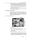
6) To allow the module SE/BTL
control input to switch the amplifier IC
between single ended (SE) and bridge-tied load (BTL) output modes, set
output mode jumper J1 to OFF. To keep the module amplifier IC in the
single-ended output mode regardless of the control input state, set jumper
J1 to ON.
7) To allow the module HP/LINE
control input to switch the amplifier IC
between using the HP pins and the LINE pins as the signal inputs, set the
input mode jumper J2 to OFF. To keep the amplifier IC in the HP input
mode regardless of the control input state, set jumper J2 to ON.
- Control Inputs
8) To allow the amplifier IC to switch from the LINE inputs to the HP inputs
when the output switches from BTL output mode to SE output mode and
vice versa, set jumper J3 to ON. To allow the inputs and output modes to
switch independently, set jumper J3 to OFF. Connect control lines to the
various module control input pins as needed:
a) SE/BTL
: A high selects the single-ended (SE) output mode; a low or
float selects the bridge-tied load (BTL) output mode.
b) HP/LINE
: A high selects headphone inputs (pins 4 and 10); a low or
float selects line inputs (pins 5 and 9).
c) SHUTDOWN
: A low shuts down the amplifier IC on the module; a high
or float allows normal operation.
d) FADE
: A low places the amplifier in FADE mode which slowly
increases/decreases the gain when leaving/entering the
SHUTDOWN state; a high or float allows a quick ramp of gain when
entering/leaving SHUTDOWN.
- Power-Up
9) Verify correct voltage and input polarity and set the external power supply
to ON.
The EVM should begin operation.
10) Adjust the signal source level as needed.
11) Adjust the BTL (speaker) volume as needed by turning the RS potentiom-
eter in the clockwise direction to increases the volume. Turn in the counter
clockwise direction to decrease the volume. The VOL pin on the right side