Quick Start List for Stand-Alone
2-5
Quick Start
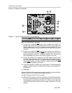
17) Adjust the SE (headphone) volume by adjusting potentiometer R6. Turn-
ing R6 in the clockwise direction decreases the voltage on the SEDIFF ter-
minal and the SE gain increases. Turning R6 in the counter clockwise di-
rection increases the SEDIFF voltage and decreases the SE volume.
18) Set the maximum possible SE gain by adjusting R7. Turning R7 in the
clockwise direction sets the limit higher; turning R7 in the counter clock-
wise direction lowers the SE gain limit.
19) Press and hold switch S1 down to place the amplifier in the SHUTDOWN
state. Release for normal operation.
2.3 Quick Start List for Stand-Alone
Follow these steps to use the TPA6011A4 EVM stand-alone or when
connecting it into existing circuits or equipment. Connections to the
TPA6011A4 module header pins can be made via individual sockets,
wire-wrapping, or soldering to the pins, either on the top or the bottom of the
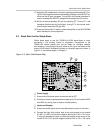
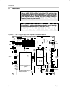
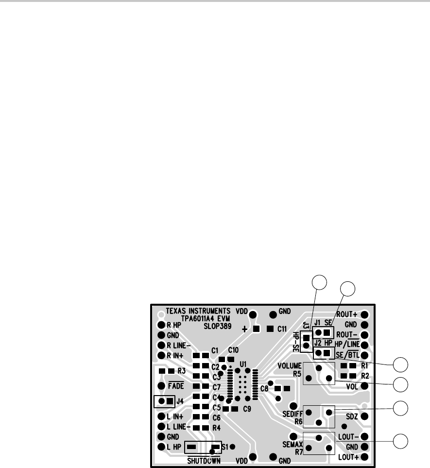
module circuit board. Numbered callouts for selected steps are shown in
Figure 2–3, and details appear in Chapter 3.
Figure 2–3. Quick Start Module Map
8
6
7
11
12
13
- Power Supply
1) Ensure that all external power sources are set to OFF.
2) Connect an external regulated power supply set to 5 V to the module VDD
and GND pins taking care to observe marked polarity.
- Inputs and Outputs
3) Ensure that audio signal source level adjustments are set to minimum.
4) Connect the right (left) positive lead of the audio source to the module
R LINE– (L LINE–) pins and the negative lead to the R IN+ (L IN+) pins.
If using the headphone inputs, connect the positive audio source to the
module R HP (L HP) and the negative lead to R IN+ (L IN+). The inputs


