


The TPA6011A4 Audio Power Amplifier Evaluation Module
3-9
Details
3.2.5 Depop Circuitry
The TPA6011A4 amplifier IC contains internal circuitry to minimize the various
transients that might appear at the output during the transition from power off
or shutdown to normal operation, or when transitioning between the SE and
BTL modes.
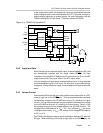
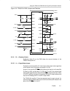
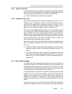
3.2.6 BTL Operation
To operate in the bridge-tied load output mode, the module SE/BTL control
input terminal must be held low. The module output signal from OUT+ must go
through the speaker load and be returned directly to OUT–, and NOT to system
ground. This requires that the OUT– line be isolated not only from system
ground, but also from the OUT– lines of any other amplifiers in the system. The
platform provides such isolated output lines from the amplifier EVM sockets
directly to separate left and right speaker connectors.
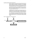
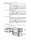
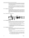
3.2.7 Single-Ended Operation
For single-ended operation, the module SE/BTL control input pin must be held
high. The speaker (or headphone) load is connected to the module OUT+
output pin through a coupling capacitor, and to platform/system ground. A
470-µF electrolytic coupling capacitor is provided on the platform in the signal
path to the headphone output jack for this purpose, and a control signal from
the platform headphone jack can be routed to the module control input pin to
switch the TPA6011A4 IC to the single-ended mode.
In the single-ended mode, the amplifiers inside the TPA6011A4 IC that drive
the OUT– lines do not operate and do not dissipate any power. The OUT– pins
go into a high-impedance state and can be left connected or allowed to float.