


The TPA6011A4 Audio Power Amplifier Evaluation Module
3-5
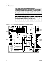
Details
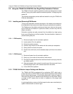
In the single-ended mode, the headphone inputs are automatically selected
and the speaker load is connected between the OUT+ terminal, through an
output coupling capacitor, to system ground. For more information, see the
TPA6011A4 amplifier IC data sheet, TI literature number SLOS392.
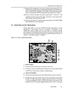
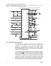
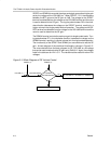
Figure 3–4. TPA6011A4 Amplifier IC
MUX
SE/BTL
MUX
HP/LINE
VOLUME
CONTROL
FADE
L LINE–
L HP
VOLUME
L IN+
R HP
R LINE–
R IN+
SEDIFF
SEMAX
3.2.2 Inputs and Gain
Each channel has two separate signal inputs, line and headphone (HP), that
are automatically selected with the output mode (SE/BTL
). An input
multiplexor in the amplifier IC selects the HP inputs when the IC is in the SE
output mode and the line inputs when in the BTL output mode.
Line and headphone inputs share common positive inputs. If using separate
line and headphone inputs, R IN+ and L IN+ should be ac-grounded through
a capacitor. If using differential inputs, line and headphone inputs must be the
same.
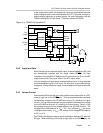
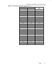
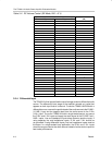
3.2.3 Volume Control
Potentiometer R5 adjusts the gain of the amplifier when the amplifier is in BTL
mode (a logic low on the SE/BTL
pin). Turning the potentiometer clockwise
increases the voltage on the VOLUME terminal (pin 21), resulting in a higher
volume. Turning the potentiometer counter-clockwise decreases the voltage
on the VOLUME terminal (pin 21), resulting in a lower volume. Table 3–1 lists
the corresponding gain for the voltage applied to the VOLUME terminal. The
voltages listed in the table are for V
DD
= 5 V. For a different V
DD
, the values
in the table scale linearly. If V
DD
= 4 V, multiply all the voltages in the table by
4 V/5 V, or 0.8.
The TPA6011A4 allows the user to specify a difference between BTL gain and
SE gain. When switching to SE mode (a logic high on the SE/BTL
pin), the