


Using the TPA6011A4 EVM With the Plug-N-Play Evaluation Platform
3-10
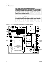
Details
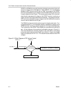
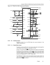
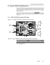
3.3 Using the TPA6011A4 EVM With the Plug-N-Play Evaluation Platform
The TPA6011A4 audio amplifier evaluation module was designed to be used
with the TI plug-n-play audio amplifier evaluation platform. It simply plugs into
socket U2.
The following paragraphs provide additional details for using the TPA6011A4
EVM with the platform.
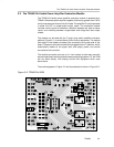
3.3.1 Installing and Removing EVM Boards
TI plug-n-play evaluation modules use single-in-line header pins installed on
the underside of the module circuit board to plug into sockets on the platform.
The EVM pins and the platform sockets are keyed such that only the correct
type of EVM can be installed in a particular socket, and then only with the
proper orientation.
Evaluation modules are easily removed from the platform by simply prying
them up and lifting them out of their sockets. Care must be taken, however, to
prevent bending the pins.
3.3.1.1 EVM Insertion
1) Remove all power from the evaluation platform.
2) Locate socket U2 on the platform.
3) Orient the module correctly.
4) Carefully align the pins of the module with the socket pin receptacles.
5) Gently press the module into place.
6) Check to be sure that all pins are seated properly and that none are bent
over.
3.3.1.2 EVM Removal
1) Remove all power from the evaluation platform.
2) Gently pry up one side of the module a small amount.
3) Change to the opposite side of the module and use the tool to pry that side
up a small amount.
4) Alternate between sides, prying the module up a little more each time to
avoid bending the pins, until it comes loose from the socket.
5) Lift the EVM off the platform.
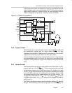
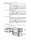
3.3.2 TPA6011A4 Module Jumper Settings and Switches
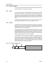
The TPA6011A4 EVM is equipped with a pushbutton SPST switch and a
jumper that acts as an SPST switch to allow module operation to be modified
to suit various requirements. In the following discussion, setting a jumper to
ON means that a shunt is installed across the two pins of the jumper. Setting
a jumper to OFF means that no shunt is installed on the jumper (see
Figure 3–6).
In typical applications, some or all of the jumper functions are controlled by the
system microcontroller or external logic.