


Using the TPA6011A4 EVM With the Plug-N-Play Evaluation Platform
3-11
Details
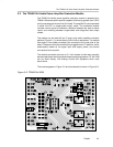
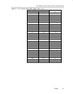
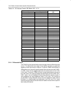
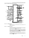
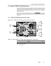
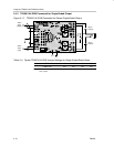
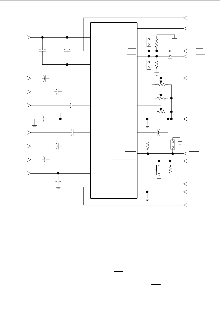
Figure 3–6. TPA6011A4 EVM Jumpers and Switches
PGND
ROUT–
PV
DD
RHPIN
RLINEIN
RIN
V
DD
LIN
LLINEIN
LHPIN
PV
DD
LOUT–
1
ROUT+
SE/BTL
HP/LINE
VOLUME
SEDIFF
SEMAX
AGND
BYPASS
FADE
SHUTDOWN
LOUT+
PGND
2
3
4
5
6
7
8
9
10
11
12
13
14
15
16
17
18
19
20
21
22
23
24
V
DD
J1
R1
100 kΩ
V
DD
J2
R2
100 kΩ
V
DD
V
DD
V
DD
C8
0.47 µF
V
DD
R3
100 kΩ
J4
S1
V
DD
C10
0.47 µF
C11
10 µF
C3
0.47 µF
C2
0.47 µF
C1
0.47 µF
V
DD
C7
0.47 µF
C4
0.47 µF
C5
0.47 µF
C6
0.47 µF
C9
0.47 µF
ROUT+
SE/BTL
HP/LINE
ROUT–
VOL
GND
FADE
SDZ
LOUT+
GND
LOUT–
GND
R HP
R LINE–
R IN
L IN
L LINE–
L HP
V
DD
J3
R4
100 kΩ
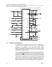
3.3.2.1 S1 — Shutdown Switch
Pushbutton switch S1 on the EVM allows the manual shutdown of the
TPA6011A4 amplifier IC.
3.3.2.2 J1 — Output Mode Jumper
To keep the module amplifier IC in the single-ended output mode regardless
of the module control input state, set jumper J1 to ON.
Jumper J1 connects the SE/BTL
output mode control input pin on the amplifier
IC directly to V
DD
, so that when J1 is ON, the IC is held in the single-ended
output mode regardless of the state of the SE/BTL module control input. When
J1 is OFF, a pulldown resistor on the module holds the IC output mode control
input pin low, keeping the IC in the BTL output mode.
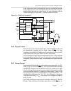
The TPA6011A4 amplifier IC has two separate inputs for each channel. An
internal multiplexor selects which input to connect to the amplifier based on the
state of the SE/BTL
pin on the IC.