


Quick Start List for Platform
2-4
Quick Start
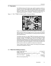
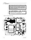
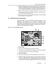
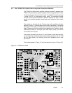
Figure 2–2. Module Preparation
13
11
12
16
17
18
19
14
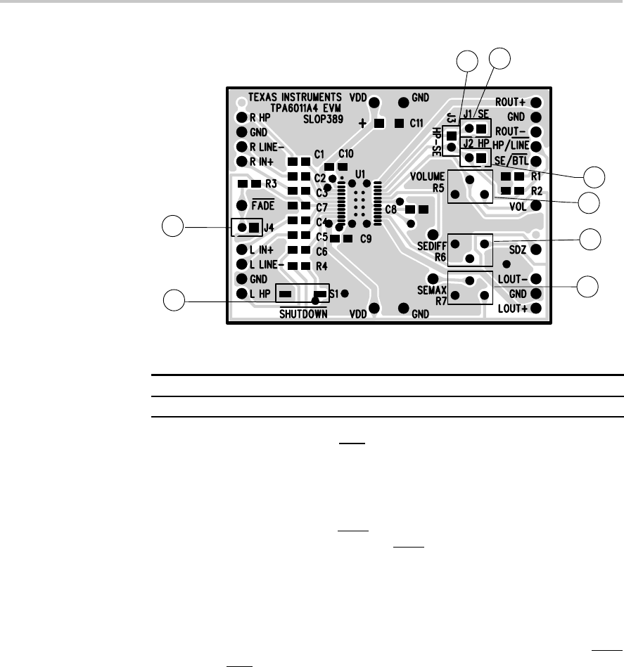
Table 2–4. Typical TPA6011A4 EVM Jumper Settings
EVM J1 J2 J3 J4
TPA6011A4 OFF OFF ON OFF
Note: ON = Shunt installed, OFF = Open
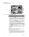
11) To allow the module SE/BTL control input to switch the amplifier IC
between single ended (SE) and bridge-tied load (BTL) output modes, set
output mode jumper J1 to OFF. To keep the module amplifier IC in the
single-ended output mode regardless of the control input state, set jumper
J1 to ON.
12) To allow the module HP/LINE
control input to switch the amplifier IC
between using the HP pins and the LINE
pins as the signal inputs, set the
input mode jumper J2 to OFF. To keep the amplifier IC in the HP input
mode regardless of the control input state, set jumper J2 to ON.
13) To allow the amplifier IC to switch from the LINE inputs to the HP inputs
when the output switches from BTL output mode to SE output mode and
vice versa, set jumper J3 to ON. To allow the inputs and output modes to
switch independently, set jumper J3 to OFF. Jumper J3 ties the HP/LINE
and SE/BTL pins together on the EVM.
14) To place the amplifier in FADE mode, install jumper J4. FADE mode slowly
ramps up or down the gain of the amplifier when leaving or entering SHUT-
DOWN mode.
- Power Up
Platform LED2 should light indicating the presence of V
DD
, and the evaluation
modules installed on the platform should begin operation.
15) Adjust the signal source level as needed.
16) Adjust the BTL (speaker) volume as needed by turning the R5 potentiome-
ter in the clockwise direction to increase the volume. Turn in the counter
clockwise direction to decrease the volume. The VOL pin on the right side
of the EVM is provided to monitor the dc voltage. See Table 3–1 for gain
settings.