


User's Manual
13
CHAPTER 1
surround back, right surround back,
right surround and one subwoofer
(LFE) output.
If your amplifi er has a choice of
inputs, we recommend using the XLR
balanced type. This gives better noise
rejection, especially for longer cable
runs.
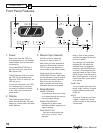
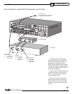
9. FM Antenna
The supplied FM antenna fi ts this
“F-type” screw-on connector. Other
antennas can be fi tted for improved
re cep tion.
10. AM Antenna
These con nec tions are for the in-
cluded AM loop antenna.
11. Ground Screw
This is commonly used for the ground
con nec tion wire of a turntable, to
prevent any hum in your speakers. It
is tied to the chassis ground, and may
be used as needed.
Note: It is not necessary or desirable
to connect this to an electrical ground.
12. Audio Inputs
These audio inputs connect to the
outputs of your turntable, DAT or
TAPE player. Any standard audio
component with a line-level output
can be con nect ed to DAT or TAPE.
Only a turntable with a moving-
magnet, or high-output moving-coil
cartridge can be connected to the
PHONO input.
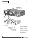
13. Audio Outputs
These audio outputs connect to the
analog record inputs of your tape
decks, such as DAT, cas sette or reel
to reel. These outputs allow you to
record the selected audio program.
Note that these also allow analog
re cord ing from digital audio sourc es.
14. 8-CH Input
These analog audio inputs can
connect to the output of an external
surround processor, or a source com-
ponent such as DVD-Audio, SACD,
or a DVD player with its own surround
decoder. You can select this as an
input from the front panel or remote
control. The eight channels of analog
audio will then pass into the TGP-5.
Note: This is designed to be a very
short analog-only signal path. DSP-
based effects such as tone controls,
bass management and DSP surround
are bypassed. This input is not avail-
able in Zone 2.
15. Stereo Outputs
FIXED MAIN is a line level output,
and the volume is not adjustable. This
can be used as a record output, or to
feed another audio system.
ZONE 2 connects to the inputs of a
stereo amplifi er to run Zone 2. The
volume and source are adjustable,
either from the front panel, or from a
remote IR sensor.
16. Digital Inputs
These inputs connect to the digital
outputs of your audio/video com po -
nents. The DVD, SAT and VID1 and
CD inputs have two op tions, optical or
coaxial. The DAT and VID2 inputs are
coaxial only.
Whenever one of these inputs is se-
lected from the front panel or remote,
the TGP-5 will au to mat i cal ly select
the digital input if there is a signal
present, otherwise it will select the
cor re spond ing analog input.
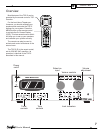
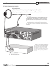
17. Main Audio Out puts
These line-level RCA outputs con-
nect to the inputs of your amplifi ers
and powered subwoofer(s). There are
outputs for front left, front right, cen-
ter, left surround, left surround back,
right surround back, right surround
and three identical subwoofer (LFE)
outputs.
18. Digital Output
This S/PDIF output is active for all
sources except the 8-channel input. It
allows you to record digital audio, for
ex am ple to a DAT or CD-R.
19. Side-Axis Outputs
These outputs provide two optional
front side channels to com ple ment
the left, center, right, surround and
surround back chan nels. They can
be turned on or off using the Speaker
Size OSD menu (see page 38).
20. Ethernet port
This Ethernet port is a Lantronix Xport
10/100T TCP/IP with confi gurable
IP address, and security. It uses a
simple ascii command set to control
the TGP-5.
An embedded webpage is included
for PC control, and monitoring via
TCP/IP Link.
There are two LEDs on the Ethernet
jack, that indicate the connection
status as shown in this table:
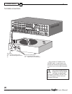
21. HDMI
Use these to connect any HDMI
components you may have in your
system. Two are inputs, and one is
an output to your HDMI-equipped TV.
No TGP-5 on screen display or audio
decoding inside the TGP-5 is avail-
able from the HDMI inputs. Always
connect a separate digital audio input
cable when using HDMI.
22. IEC Linecord Socket
The TGP-5 comes with a de tach able
linecord which connects here.
Plug the linecord into an AC wall
socket or power strip which is cor-
rectly confi gured with the voltage
spec i fi ed for your model.
23. Power Switch
If this is switched off, the TGP-5 will
be off, and cannot be turned on, even
with the front panel power switch.
In normal operation, leave this switch
on. Turn it off if you will not be using
the TGP-5 for extended periods.
Rear Panel Fea tures
LEFT LED RIGHT LED
Color Meaning Color Meaning
Off No Link Off No
Activity
Amber 10 Mbps Amber Half
Duplex
Green 100
Mbps
Green Full
Duplex