


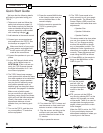

User's Manual
12
CHAPTER 1
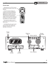
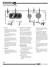
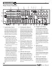
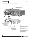
6. Triggers and Relay
The relay switch is normally open,
and it will close after a short delay,
when selecting a source. This can be
used in in stal la tions to trigger video
screen deployment, or other custom
purposes. The OSD INPUTS menu
allows you to choose which inputs will
activate the relay.
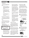
The +12 VDC outputs are on when-
ever their zone is enabled. Sunfi re
amplifi ers and subwoofers have a +12
VDC input which allows them to be
turned on automatically by the TGP-5.
The 1/8” mini-jack is wired in parallel
with the terminals. Do not exceed a
current draw of 500 mA total for both
outputs.
7. RS-232 Port
This connects to the serial port of a
home computer, allowing the TGP-5
Flash memory software to upgraded.
Latest software can be downloaded
from www.sunfi re.com.
The port can also connect to the se-
rial port of a Home Theater Controller,
allowing the TGP-5 to be operated
remotely.
8. XLR Audio Outputs
These line-level balanced XLR
outputs connect to the XLR inputs
of your amplifi ers and powered
subwoofer. The outputs are: front left,
front right, center, left surround, left
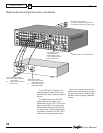
Rear Panel Fea tures
1. Audio/Video Inputs
These audio, composite-video and S-
video inputs con nect to the outputs of
your audio video com po nents. When
these inputs are selected, the audio
will be heard in your system and the
video will be seen on the TV screen.
VID2 can be used for a second VCR.
2. Audio/Video Outputs
MAIN: connects to the inputs of a TV
monitor, where the video of any
selected input and the On Screen
Display (OSD) can be viewed. The
audio con nec tions allow you to
listen to any selected audio source
through your TV’s speak ers.
VCR: connects to the inputs of a VCR
to allow recording.
VID2/MON2: connects to the input of
a second VCR for recording, or to
a second TV. When confi gured in
the OSD for “VID2,” this output is
muted whenever the VID2 input is
selected. This prevents feedback;
also there is no OSD then on
this output. When confi gured for
“MON2,” the output is always ac-
tive, the same as the Main output.
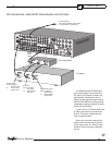
Note: Analog audio signals are pres-
ent at these L and R outputs even if
a digital input has been selected. The
output is a 2 channel downmix if the
digital source is more than 2 chan-
nels.
3. Component Video In
These inputs con nect to the compo-
nent-video outputs of your DVD, SAT
or other video source (VID1) if they
have this advanced capability. When
these inputs are se lect ed, the TGP-5
will au to mat i cal ly route any video
signals going into these jacks to the
component video outputs. Note that
component video provides the best
picture compared to composite or
S-video. The TGP-5 can also switch
HDTV signals.
4. Component Video Out
If your TV Monitor has component
video inputs, connect them to these
outputs. If you select DVD, SAT or
VID1, then any video signals going to
the component inputs will
pass through to your TV monitor. The
TGP-5 can also up-convert compos-
ite video and S-video from the other
inputs.
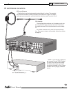
5. Infrared (IR) Inputs
These are used in custom in stal -
la tions to control the Main Zone and
Zone 2 from a remote location. The
input accepts 1/8” mono mini-jacks
from standard remote control IR
equipment, such as those made by
Xantech and other companies. The
remote sensors can be in a different
room, or in a preferred location in your
main room.
1234657 8
9
10
11
12 13 14 15 16 18 19 2217 20 21 23