


37
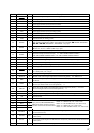
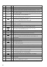
Pin No. Pin Name I/O Description
35 DSPLAT O
Serial data latch pulse output to the CXD2726Q (IC100)
36 DSPRST O
Reset signal output to the CXD2726Q (IC100) “L”: reset
37 NC O
Not used (open)
38 DVCC —
Power supply terminal (+5V) (for D/A converter)
39 DVSS —
Ground terminal (for D/A converter)
40, 41 NC O
Not used (open)
42 AVCC
— Power supply terminal (+5V) (for analog system)
43 AVRH
I Reference voltage (+5V) input terminal (for A/D converter)
44 AVRL
I Reference voltage (0V) input terminal (for A/D converter)
45 AVSS
— Ground terminal (for analog system)
46 KEYIN0
I
Key input terminal (A/D input) (LSW901 to LSW908, S901 to S904)
OFF, SOURCE, SOUND EQ, MENU, PTY DSPL, LIST, ENTER, o MODE, SEEK/AMS -
. m + > M, DISC/PRST +, DISC/PRST – keys input
47 KEYIN1
I
Key input terminal (A/D input) (LSW801, LSW909 to LSW917)
Z, DSO, TA, AF, 6 to 3 SHUF 2, REP 1 keys input
48 RCIN0
I Rotary remote commander key input terminal (A/D input)
49 DSTSEL I
Destination setting terminal (A/D input) “L”: XR-C7500R/C7500RX: TYPE A,
“M”: XR-C7500R/C7500RX: TYPE C, “H”: XR-C7500R/C7500RX: TYPE B
50 QUALITY
I Noise level detection signal input at SEEK mode (A/D input)
51
FMAGC I
FM AGC detection signal input from the FM/AM tuner unit (TUX1) (A/D input)
52 MPTH
I Multi-path detection signal input from the RDS decoder (IC50) (A/D input)
53
VSM I FM and AM signal meter voltage detection input from the FM/AM tuner unit (TUX1) (A/D input)
54 VCC —
Power supply terminal (+5V)
55 AMP ON O
Standby on/off control signal output to the power amplifier (IC700)
“L”: standby mode, “H”: amp on
56 NS-MASK O
Discharge control signal output for the noise detection circuit “H”: discharge
57 MTLOUT O METAL on/off control signal output to the CXA2510AQ (IC250) “H”: METAL on
58 REEL I
Rotation detect signal input from supply reel sensor and take-up reel sensor on the deck
mechanism
59 LM-EJ O
Motor drive signal output to the loading/tape operation motor drive (IC201) “H” active
(For the eject direction and reverse side operation) *1
60 LM-LOD O
Motor drive signal output to the loading/tape operation motor drive (IC201) “H” active
(For the loading direction and forward side operation) *1
61 CM ON O
Capstan/reel motor (M901) drive signal output terminal “H”: motor on
62 TAPE ON O
Tape system power supply on/off control signal output terminal “H”: tape on
63 VSS —
Ground terminal
64 NC I
Not used (fixed at “L”)
65 POS0 I
66 POS1 I
67 POS2 I
68 POS3 I
69
FLASH-W
I
Internal flash memory data write mode detection signal input terminal “L”: data write mode
Not used (fixed at “H”)
70 I2C SDA I/O
Two-way data I
2
C bus with the FM/AM tuner unit (TUX1), RDS decoder (IC50) and electrical
volume (IC10)
71 I2C SCL O
I
2
C bus clock signal output to the FM/AM tuner unit (TUX1), RDS decoder (IC50) and electrical
volume (IC10)
72 RCIN1
I Rotary remote commander shift key input terminal
Tape position (EJECT/FF/REW/REV/
FWD mode) detect input from the tape
operation switch on the deck mechanism
POS0: “L”: EJECT mode, “H”: others mode
POS1: “L”: FF and FWD mode, “H”: others mode
POS2: “L”: REW mode, “H”: others mode
POS3: “L”: REV and EJECT mode, “H”: others mode