


9-34
DFP-3000
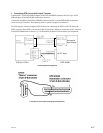
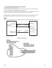
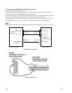
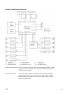
2. Connecting the DTS-6D to the AUX2 input terminal
Connection when using the AUX2 terminal
Connect Pin 10 (GND when Digital output) of the DTS-6D Automation connector and Pin 35 (Lip-,
AUX2 Fallback input) of the DFP-D3000 Automation connector.
Connect Pin 13 (GND) of the DTS-6D Automation terminal and Pin 14 of the DFP-D3000 Automation
connector (Logic Common). The following shows a specific example of connections.
For audio signals, use a DTS-6D analog output connector (D-sub, 25 pin) to connect the AUX2 of the
DFP-D3000. Refer to Section 9.7.5 of this manual for details of the connector pin assignment.
n
When connecting the DTS-6D to the DFP-D3000, the DTS Automation Interface board is not necessary.
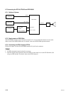
1. Overall System Configuration
2. Connection of Controller
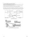
Pin 10 (GND
when Digital)
Pin 13 (GND)
Pin 35 (Lip -,
AUX2 Active)
Pin 14 (Logic
Common)
Automation
Connector
Analog Output
Connector
Automation
Input /Output
AUX2 Input
D-sub 25 pin
Connector
D-sub 25 pin
Connector
D-sub 25 pin
Connector
D-sub 37 pin
Connector
DTS Inc. DTS-6D DFP-D3000