


9-25
DFP-3000
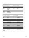
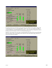
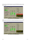
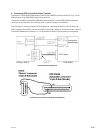
5. Audio input/output level adjustments
Since the channel output adjustment and output bass and treble adjustments of the CP-500 is done on the
output board (in the analog domain), these settings will also affect SDDS. Therefore, adjust the B-chain
of the CP-500 prior to the B-chain of the DFP-D3000.
To obtain an optimum gain structure, select _10 dBu reference as the DFP-D3000 reference output level,
and increase the channel level trims to approximately +2 dB to match the 300 mV reference input level of
the CP-500.
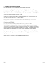
With this set-up, the master fader of the CP-500 will not affect the playback levels for formats played
through the DFP-D3000 and vice versa.
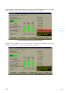
6. DFP-D3000 settings
Basically, as the DFP-D3000 is used only for SDDS reading, use it at the shipment settings. Do not adjust
the DFP-D3000 equalizer and surround delay settings, but set them at the CP-500. It is recommended that
the DFP-D3000 SDDS Preset (Preset 8) EQ and Surround Delay settings are set to OFF.
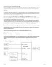
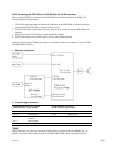
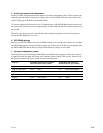
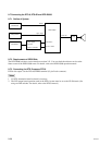
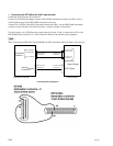
7. Using as a changeover system
When using the system combining the DFP-D3000 and CP-500 in the changeover format, it is necessary
to supply the motor start pulse and change over command signals for the CP-500 as well. Therefore, add
the following signals to the control signal line and connect the cables.
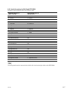
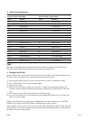
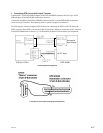
Projector DFP-D3000 Automation I/O Connector CP-500 Motor Start Connector
(D-sub Connector, 37pin, Female) (D-sub Connector, 9pin, Female)
Signal Pin No. Function Pin No. Function
Projector 1 Motor Start Pin 12 Motor 1 Pin 1 Motor Start Projector 1
Projector 2 Motor Start Pin 13 Motor 2 Pin 9 Motor Start Projector 2
Picture Gate Select Pin 19 C/O command, tally Pin 3 Change Over Relay
Common Pin 16 Tally Common Pin 5 GND