


9-19
DFP-3000
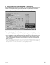
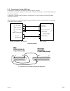
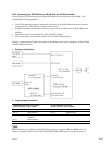
2. Logic wiring connections
DFP-D3000 Automation I/O Connector CP-500 Automation Connector
(D-sub Connector, 37 pin, Female) (D-sub Connector, 25 pin, Female)
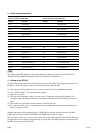
Pin No. Function Pin No. Function
Pin 8 Preset 5 Select (NR2) Pin 3 SK3 format select (Dolby SR)
Pin 9 Preset 6 Select (AUX 1) Pin 4 SK4 format select (Dolby Digital)
Pin 14 Logic Common Pin 12 Ground
Pin 11 Preset 8 Select (SDDS) Pin 6 SK6 format select (Non Sync 1)
- Shorted to -
Pin 32 SDDS data OK
Pin 36 SDDS data not OK Pin 2 SK2 format select (Dolby A)
Pin 15 Logic Common
- Shorted to -
Pin 34 AUX1 Digital Data OK
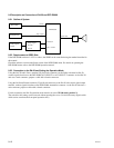
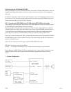
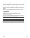
3. Audio wiring connections
DFP-D3000 AUX input 1/2 CP-500 Main / LF output connector
(D-sub connector, 25 pin, Female) (15 pin Phoenix type, Male)
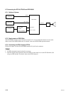
Pin No. Function Pin No. Function
Pin 1 Left Ground _ No Connection
Pin 2 Left Hot (+) 1 Left Channel
Pin 4 Center Ground _ No Connection
Pin 5 Center Hot (+) 5 Center Channel
Pin 7 Right Ground _ No Connection
Pin 8 Right Hot (+) 3 Right Channel
Pin 9 Left Surround Ground _ No Connection
Pin 10 Left Surround Cold (_) 8 Signal Ground
Pin 11 Right Surround Cold (_) 10 Signal Ground
Pin 12 Subwoofer Cold (_) 12 Signal Ground
Pin 13 Subwoofer Ground _ No Connection
Pin 14 Left Cold (_) 2 Signal Ground
Pin 17 Center Cold (_) 6 Signal Ground
Pin 20 Right Cold (_) 4 Signal Ground
Pin 22 Right Surround Ground _ No Connection
Pin 23 Left Surround Hot (+) 7 Left Surround Channel
Pin 24 Right Surround Hot (+) 9 Right Surround Channel
Pin 25 Subwoofer Hot (+) 11 Subwoofer Channel
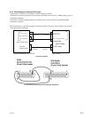
n
The inputs of the DFP-D3000 are professionally balanced, whereas the outputs of the CP-500 are not.
Therefore shielded wires should be connected to all DFP-D3000 audio grounds.