


3-3
DFP-3000
Wiring of other equipment.
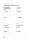
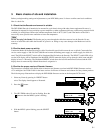
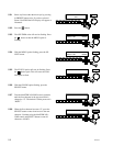
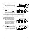
This following is an illustration of the DFP-D3000 rear panel.
Note that these D-Sub connectors have metric (M2.5 x .45) jack screw receptacles and require mating
connectors with metric jack screws. A kit of such connectors is provided with each DFP D3000. Do not
use standard D-Sub connectors with 4-40 jack screws.
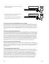
Cinema processors.
Refer to the list of available Tech Notes in the Appendix of this Guide for instructions on correct audio
and logic interconnections to other cinema processors. Note that Sony connectors use the THX
®
pinout
convention, but other equipment may not. Therefore, pre-fabricated cables or cables made with flat ribbon
computer-type cable are generally not acceptable for use with the DFP-D3000. The DFP-3000 cinema
processor is capable of exceptional performance; do not degrade this by using inferior cables. Sony
strongly recommends that all audio interconnections in your cinema sound rack be made using high
quality audio-grade twisted pair shielded cables or individually shielded multipair cable. Contact your
dealer for information regarding pre-wired audio cables for the DFP-D3000, available from several
cinema accessory distributors.
Non-sync inputs.
The non-sync inputs of the DFP-D3000 are on consumer standard RCA-type connectors. One dedicated
non-sync input is available. If additional non-sync inputs are required, the MIC1 input can easily be
configured for line level operation, and the two eight-channel AUX inputs can serve as additional line
level inputs for electronic projectors, DVD, magnetic film dubbers, and other external analog sound
sources.
Microphone inputs.
The MIC1 and MIC2 inputs have built in microphone preamplifiers, so that external mixers or line-
matching devices are not required to directly connect a microphone level input. Input connections are
balanced on a single D-Sub 9-pin female connector. 48-volt phantom power for condenser microphones is
available, and can be switched on using the setup software or the front panel. See the instructions for MIC
configuration later in this Guide for more detailed information.
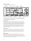
OUTPUT INPUT PROJECTOR I/0
CONTROL I/0
MONITOR OUTPUT MIC INPUT
NON-SYNC
R L
1 READER 2
SYSTEM OUTPUT
REMOTE
LEVEL
CONTROL
AUX INPUT 1 1 OPTICAL 2
AUX INPUT 2PHONES AUTOMATION
RS-232C RS-422
15V
To balanced inputs
of booth monitor
From Mic 1
and Mic 2
From Non-sync
player
From Projector 1
optical reader
To power amps
and loudspeakers
To phones
and HI
From other
cinema processors
Automation logic
inputs and outputs
To laptop PC via
null modem cable
Backup
supply
Chassis
ground
From Projector 1
R3000 Reader
120 / 230
VAC