


2
MZ-B100
SAFETY-RELATED COMPONENT WARNING!!
COMPONENTS IDENTIFIED BY MARK 0 OR DOTTED LINE
WITH MARK 0 ON THE SCHEMATIC DIAGRAMS AND IN THE
PARTS LIST ARE CRITICAL TO SAFE OPERATION.
REPLACE THESE COMPONENTS WITH SONY PARTS WHOSE
PART NUMBERS APPEAR AS SHOWN IN THIS MANUAL OR IN
SUPPLEMENTS PUBLISHED BY SONY.
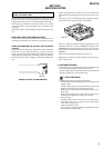
Flexible Circuit Board Repairing
• Keep the temperature of the soldering iron around 270°C during
repairing.
• Do not touch the soldering iron on the same conductor of the
circuit board (within 3 times).
• Be careful not to apply force on the conductor when soldering or
unsoldering.
Notes on chip component replacement
• Never reuse a disconnected chip component.
• Notice that the minus side of a tantalum capacitor may be dam-
aged by heat.
CAUTION
Use of controls or adjustments or performance of procedures
other than those specified herein may result in hazardous
radiation exposure.
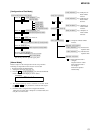
1. SERVICING NOTES ....................................................... 3
2. GENERAL .......................................................................... 4
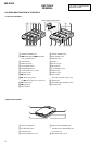
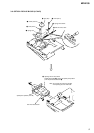
3. DISASSEMBLY
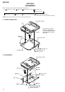
3-1. Panel (Lower) ASSY..................................................... 6
3-2. Main Board ................................................................... 6
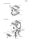
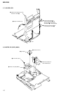
3-3. Cabinet (Belt) Section................................................... 7
3-4. Key Board Unit ............................................................. 7
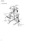
3-5. Mechanism Deck .......................................................... 8
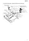
3-6. Optical Pick-up Block (LCX-4R) ................................. 9
3-7. Holder ASSY .............................................................. 10
3-8. Motor, DC (Sled) (M602) ........................................... 10
3-9. “Motor, DC (Spindle) (M601)”,
“Motor, DC (Over Write Head Up/Down) (M603)” ... 11
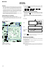
4. TEST MODE .................................................................... 12
5. ELECTRICAL ADJUSTMENTS ............................... 19
6. DIAGRAMS
6-1. Explanation of IC Terminals ....................................... 24
6-2. Block Diagrams (Main Section (1/3) .......................... 30
6-3. Block Diagrams (Main Section (2/3) .......................... 31
6-4. Block Diagrams (Main Section (3/3) .......................... 32
6-5. Printed Wiring Board (Main Section (1/2)) ................ 33
6-6. Printed Wiring Board (Main Section (2/2)) ................ 34
6-7. Schematic Diagram (Main Section (1/4)) ................... 35
6-8. Schematic Diagram (Main Section (2/4)) ................... 36
6-9. Schematic Diagram (Main Section (3/4)) ................... 37
6-10. Schematic Diagram (Main Section (4/4)) ................... 38
7. EXPLODED VIEW
7-1. Panel (Lower) Section................................................. 42
7-2. Panel (Upper Lid) Section .......................................... 43
7-3. Cabinet (Belt) Section................................................. 44
7-4. Mechanism Deck Section (MT-MZB100-171)........... 45
8. ELECTRICAL PARTS LIST ....................................... 46
TABLE OF CONTENTS
General
Power requirements
DC 3V
LR6 (size AA) alkaline dry battery (world model only)
Battery operation time
Battery life
1)
When recording
2)3)
(Unit: approx.hours) (JEITA
4)
)
Recording mode Approx. hours
Stereo 9
LP2 Stereo 12.5
LP4 Stereo 15
MONO 12
1)
The battery life may be shorter due to operating conditions
and the temperature of the location.
2)
When using a Sony LR6 (SG) “STAMINA” alkaline dry
battery (produced in Japan). Recording time may differ
according to the alkaline batteries.
3)
When recorded with the built-in microphones.
4)
Measured in accordance with the JEITA (Japan Electronics
and Information Technology Industries Association) standard.
When playing
1)
(Unit: approx.hours) (JEITA
2)
)
Recording mode Speaker
3)
Headphones
4)
Stereo 25.5 34.5
LP2 Stereo 27 39.5
LP4 Stereo 30 43
MONO 30 43
1)
When using a Sony LR6 (SG) “STAMINA” alkaline dry
battery (produced in Japan).
2)
Measured in accordance with the JEITA (Japan Electronics
and Information Technology Industries Association) standard.
3)
When played using the built-in speaker.
3)
When played using headphones.
Dimensions
Approx. 105.7 × 80.0 × 24.9 mm (w/h/d)
(4
1
/4 × 3
1
/8 × 1 in.) not incl. projecting parts and controls.
Mass
Approx. 160 g (5.7 oz) (main unit only)
Supplied accessories
Remote control (1)
Headphones (1)
Carrying pouch (1)
Hand strap (1)
Sony LR6 (size AA) alkaline dry battery (1)
1)
The LINE IN (OPTICAL) jack is used to connect either a digital
(optical) cable or a line (analog) cable.
2)
Measured in accordance with JEITA.
Design and specifications are subject to change without notice.