Chapter 3 Using the Unit as a Player in an Editing System
Chapter 3 Using the Unit as a Player in an Editing System 33
GB
MONITOR
AUDIO
VIDEO
OUT 2
(SUPER)
REMOTE
REF. VIDEO IN
REF. VIDEO INPLAYER
RECORDER
REMOTE
REF. VIDEO INPUT
REF. VIDEO OUT REF. VIDEO OUT
REF. VIDEO OUT
MONITOR
VIDEO
MONITOR
AUDIO
Y, R-Y, B-Y OUTPUT
VIDEO OUTPUT
AUDIO CH-2/4 OUTPUT
AUDIO CH-1/3 OUTPUT
Y, R-Y, B-Y IN
VIDEO IN
AUDIO CH-2 IN
AUDIO CH-1 IN
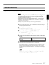
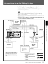
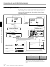
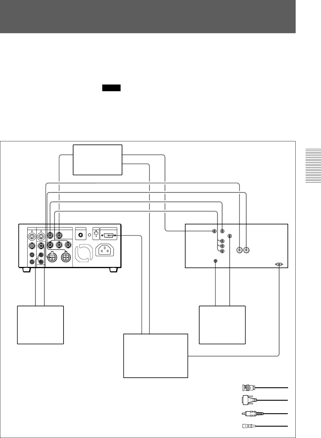
Connections for a Cut Editing System
The following figure shows a cut editing system configuration that uses
this unit as the player and a DSR-85/85P as the recorder.
For details of connecting devices other than the DSR-40/40Ps, refer to the
instruction manual of each device.
Notes
• When S-video or composite input is selected, S-video or composite
output is a through signal.
• The preroll time of the setting on the RM-450/450CE is required for more
than five seconds.
• Set RS-422 CUE-UP MODE to WITH VIDEO in the DSR-40/40P’s SET
UP menu for improving the editing accuracy.
Video signal
generator
Source video
monitor
RM-450/450CE
Editing control
unit
Main video
monitor
DSR-40/40P
(player)
Audio input
Composite video input
Audio input
Composite
video input
DSR-85/85P
(recorder)
1
4
4
1
1
1
1
2
31
2
1
3
1 75 Ω coaxial cable (not supplied)
2 9-pin remote control cable (not
supplied)
3 Cable with RCA phono plugs (not
supplied)
4 Cable with XLR connectors (not
supplied)
When you select assemble or insert
editing mode on the editing controller, the
EDIT MODE indicator lights on the front
panel of the recorder and the recorder
automatically enters the selected editing
mode.


