


1-68
DFS-700/700P
Chapter 6 System Connections and
Settings
6-6
Chapter 6 System Connections and Settings
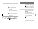
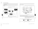
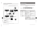
When using the BVE-2000
Control the M/E and downstream keyer through the 9-pin connector. You
can control M/E and downstream keys simultaneously.
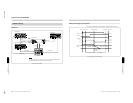
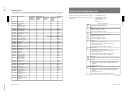
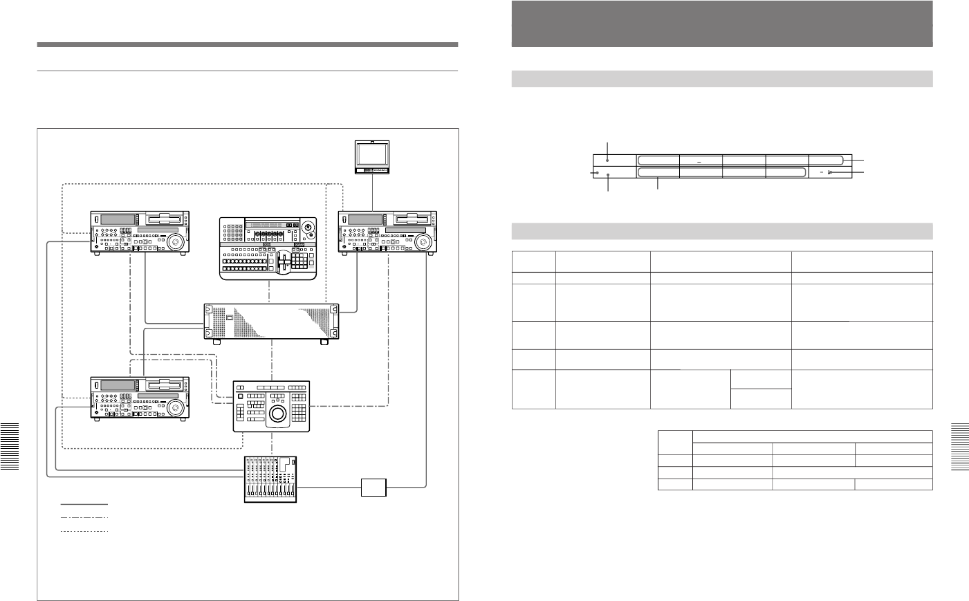
A/B roll editing system connections (2) — using the BVE-2000
Player VCR A
VIDEO OUT VIDEO
IN
VIDEO
OUT
AUDIO
IN
REMOTE
VIDEO OUT
REMOTE
REMOTE
PGM OUT
LINE OUT
LINE IN
LINE IN
VIDEO
INPUT
VIDEO
INPUT
VTR
VTR
REF IN
VTR
REF
VIDEO
IN
REF
VIDEO
IN
EDITOR
EDITOR
VIDEO SW’ ER
REF
VIDEO
IN
BLACK
BURST
OUT
AUDIO
LINE
OUT
AUDIO
LINE
OUT
2
2
4
33
1
1
3
3
1
Player VCR B
Recorder VCR
DFS-700/700P control panel
DFS-700/700P
processor
SRP-L300 Delay Unit
SRP-V200R Audio Mixer
BVE-2000 Editing Control Unit
Video and audio signals
Control signals
Black burst signal (reference
synchronizing signal)
Cables used
1 These depend on the type of VCR being connected. Check with the instructions
supplied with the VCR.
2 XLR (3-way) cables
3 RCC/5G/10G/30G 9-pin remote control cables
4 RCC11A audio mixer control cable
Connections for an A/B Roll Editing System
Chapter 6 System Connections and
Settings
Chapter 6 System Connections and Settings
6-7
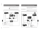
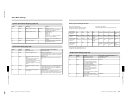
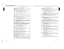
Setup Menu Settings
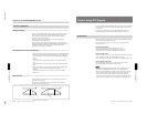
Setup Menu Organization
The setup menu is divided into eight pages, and each appears as shown in
the following example.
Example display:
SYS
P 1/8
SCREEN
4:3
PRE RD
OFF
PORTS
PVE500
TALLY
OFF
CpnIN
IN 4
System Setup (page 1/8)
F3(PORTS) setting and control
Menu name
Settings
Page
Values
To submenu
Button
Setting Meaning Values
(First value is factory default.)
F1
SCREEN
Set screen aspect ratio. 4:3/16:9
F2 PRE RD Toggle preread editing on/off.
When this is on, a “P” appears at the
beginning of line two of the menu
display.
OFF/ON
F3 PORTS Select type of editor connected to
EDITOR connector.
(See table below.)
PVE-500/BVE-600/GPI
(Select “PVE500” when a BVE-2000 is
connected.)
F4
TALLY Toggle rear panel tally output signal on/
off.
OFF/ON
F5
CpnIN
(Only appears when
optional BKDF-702/702P
is installed.)
Assignment of
numbers to rear panel
COMPONENT
connectors
5
/
1
to
8
/
4
IN1-4 r: assign 1
to 4.
1-4/5-8
To confirm displayed assignment, press
F3(OK); to cancel press F5(CANCEL).
IN5-8 r: assign 5
to 8.
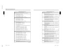
Values Valid control for each connector
EDITOR connector GPI/T 1 GPI/T 2
PVE-500 DVS control – DSK transitions
BVE-600 – Auto transitions
GPI – Auto transitions DSK transitions
A “P” appears here when
preread editing is on.