


1-64
DFS-700/700P
Chapter 5 Control From Editing
Control Units
5-12
Chapter 5 Control From Editing Control Units
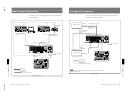
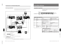
A/B Roll Editing
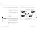
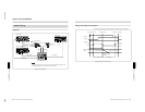
Signal flow
The flow of signals in A/B roll editing is as follows.
For more information about connections, “see Connections for an A/B Roll
Editing System” (page 6-5).
Signal flow in A/B roll editing
Player VCR A
PGM OUT
VIDEO
INPUT
VIDEO
INPUT
Recorder VCR
Foreground bus
video
DFS-700/700P
Player VCR B
Background bus
video
GPI signals
Control signal
Control signal
Control signal
Editing control unit
Note
To improve editing accuracy, supply a reference sync signal to the editing control unit and
the VCRs from the BLACK BURST OUT connectors on the DFS-700/700P.
Control Using GPI Signals
Chapter 5 Control From Editing
Control Units
Chapter 5 Control From Editing Control Units
5-13
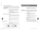
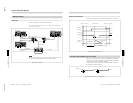
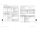
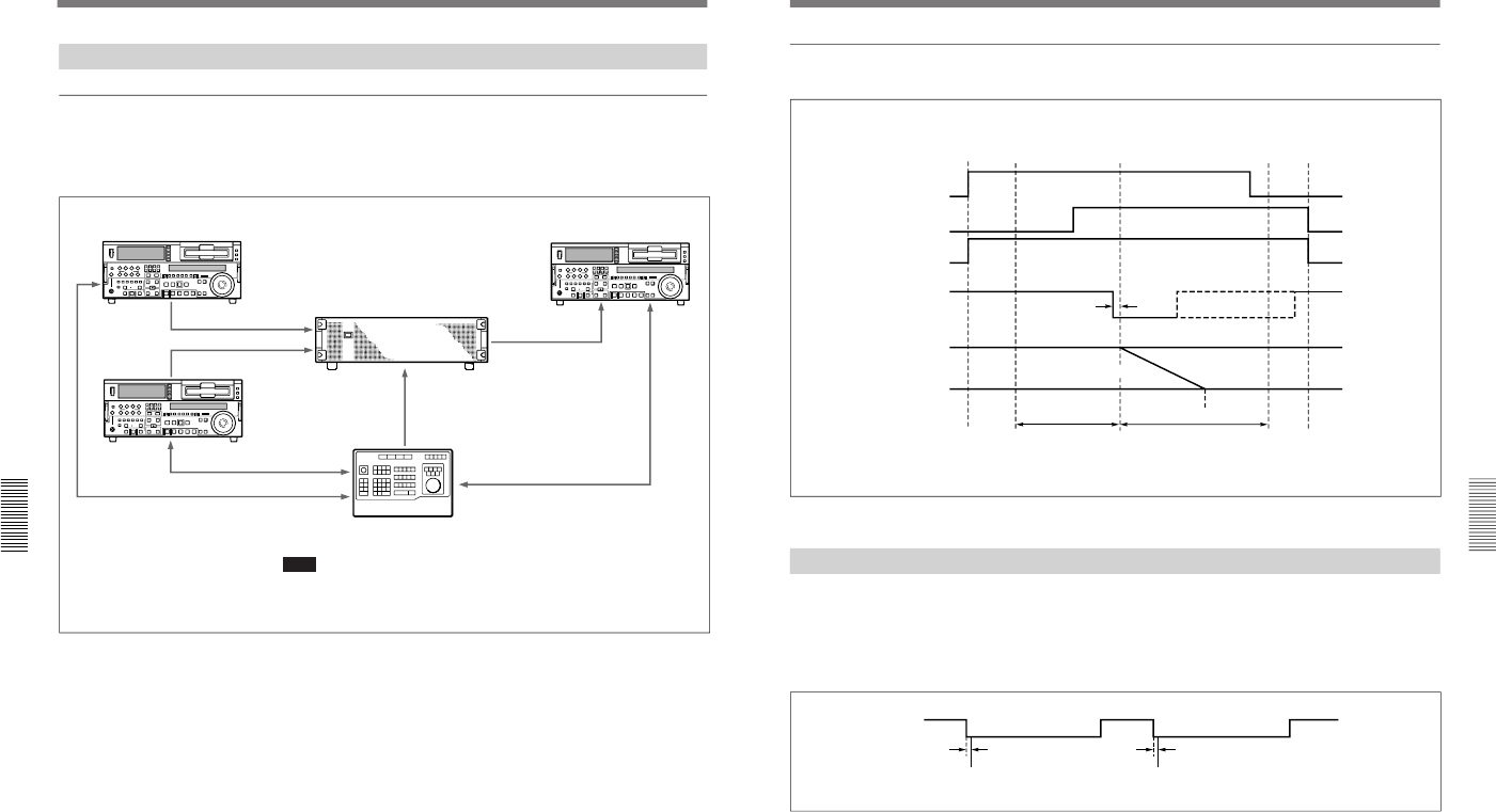
Timing of the GPI signal
The timing of the GPI signal from the editing control unit is as follows.
Timing of GPI signal in A/B roll editing
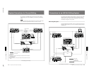
Turning a Downstream Key On and Off
If in page 1 of the setup menu you have set F3(PORTS) to “PVE-500” or
“GPI” then you can turn a downstream key on and off using a GPI signal
input to the T2 connector on the DFS-700/700P.
As shown below, the downstream key is turned alternately on and off at
the falling edge of the GPI signal.
Turning a downstream key on and off — GPI signal timing
VCRs start
IN point
Effect start point
OUT point
VCRs stop
Player A
Player B
Recorder
GPI signal
3 frames
PGM OUT
signal
Background bus image
Foreground bus
image
Preroll
Execution of
effect (transition)
Postroll
A-roll period
B-roll period
GPI signal
3 frames
3 frames
DSK ON
DSK OFF