


10
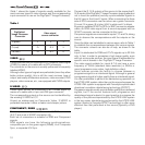
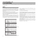
Table 1
shows the types of signals usually available for the
most common types of video sources and the corresponding
input connectors to use on the DigiOptic™ Image Processor).
Table 1
DigiOptical
Image Processor
Connector
Y (green) Y
Cr (red) P
Cb (blue)
R
Y
R-Y
Y
V
P
B
B-Y U
Video signal
source connector
VIDEO
These inputs should be connected to a Composite Video signal
(CVBS) by means of a cable with an RCA connector.
The connector on the source is usually yellow and is frequently
labelled VIDEO.
Although other types of signals are preferable (since they allow
better picture quality), this is still the most common type of
output, and nearly all television receivers, video-recorders, DVD
players, video cameras, etc., are equipped with CVBS outputs.
S-VIDEO
These inputs should be connected to an S-Video signal by
means of a cable with a 4-pin mini-DIN type connector.
The corresponding output on the source can be identified by
the wording S-VIDEO or Y/C.
Almost as widespread as Composite Video, S-VIDEO is
preferable because it offers a clearer and sharper picture.
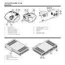
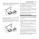
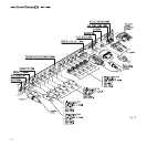
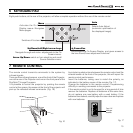
COMPONENT / RGBS
These inputs are composed of three sets of 5 RCA connectors
(5,6,7) and a set of 5 BNC connectors (8).
Each set of connectors is suitable for RGB and Component
signals.
RGB signals can have the following synchronisations:
composite sync on the green signal (RGsB), H+V Composite
Sync, or separate H/V Sync.
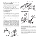
Connect the R, G, B outputs of the source to the respective R,
G, B inputs of the DigiOptic™ Image Processor (paying attention
not to invert the positions) and any synchronisation signals to
the HV input or the H and V inputs. When connecting the three
sets of RCA connectors use the colours as a guide: connector
R is red, G is green, B is blue, H/HV is white and V is black.
By using a suitable SCART to RCA (or BNC) connector adapter
cable, an RGB video signal from a source equipped with an
SCART connector can be connected to this input.
Component signals are connected to inputs Y, Cr and Cb, taking
care to observe the correspondence with the outputs on the
source.
Since the latter can be labelled in various ways, refer to
Table 1
to establish the correspondence between the various signals.
The connector colours can also be of help, as shown in the
table.
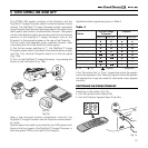
Input 5 is dedicated for RGB and YCrCb signals up to 32 KHz
only. In fact, in order to guarantee a high image quality, even
with not so accurate sources, the input signal is elaborated by
specific circuit boards in the DigiOptic™ Image Processor.
The video signal suitable for inputs 6-7-8 can have a scan
frequency of 15KHz (standard video resolution) or 32KHz or
more (progressive scan video, high definition video).
Some sources provide the facility to choose between a
progressive signal or an interlaced signal. Although in general
a progressive signal is higher quality than an interlaced signal,
it is often preferable to perform the deinterlacing operation on
the HT300 LINK system rather than on the source because the
HT300 LINK system is equipped with Faroudja’s sophisticated
directional correlation deinterlacing technology (DCDi™).
Progressive signals usually provide better quality than interlaced
signals, but if the source features both progressive and
deinterlaced signal outputs it is good practice to compare the
quality of the pictures reproduced by the HT300 LINK system
in the two cases: deinterlacing performed by the HT300 LINK
system (thanks to Faroudja DCDi™ technology) is often more
effective than that performed at the source (typically a DVD
player).