


8
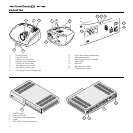
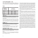
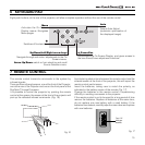
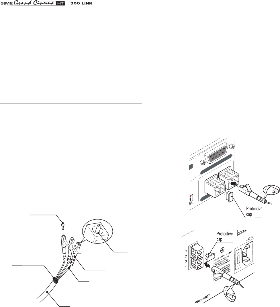
Protective cap
Separation point
Cable
Fibre
Connector
Ferrule
CAUTION: In the case of ceiling or wall mounting using a
suspension bracket, follow the instructions carefully and comply
with the safety standards you will find in the box together with
the bracket. If you use a bracket different to the one supplied
by SIM2 Multimedia, you must make sure that the projector is
at least 65 mm (2-9/16 inch) from the ceiling and that the bracket
is not obstructing the air vents on the lid and on the bottom of
the projector.
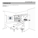
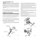
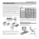
Position the projector the desired distance from the screen:
the size of the projected image is determined by the distance
from the lens of the projector to the screen and the zoom setting.
See “Appendix C”: Projection distances” for more information.
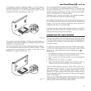
CONNECTING THE TWO UNITS
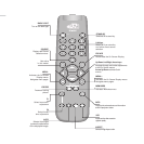
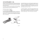
The system can be fully controlled using the supplied IR
(infrared) remote control handset. There is a single remote
control for both the DigiOptic™ Image Processor and the
Projector; the remote control can be directed towards either
unit since they are both equipped with an IR sensor.
The connection between the two units is made with a single
cable containing three fibre optic cables each terminating in
an LC connector. The standard cable length of 20m will be
sufficient for most installation requirements.
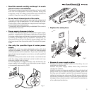
During installation of the fibre optic cable:
• The individual optical cables are delicate: always handle
the main cable without touching the individual optical cables
(Fig. 7)
.
Never pull the individual optical cables or connectors; if
necessary, you may pull the main three-core cable.
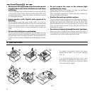
• Only remove the cap protecting the connector ferrule
immediately before inserting the connector; if the ferrule is
allowed to come into contact with foreign material it may be
damaged, making the connector unusable.
• Take particular care when inserting fibre optic connectors
in their respective sockets on the rear panel of the
DigiOptic™ Image Processor and the rear panel of the
Projector.
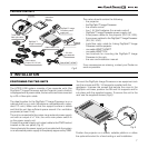
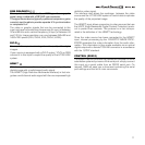
• Make sure that the single optical cables are not switched:
the numbers on the cables must match the numbers on the
connectors
(Fig.8-9)
.
• Check that the connectors are correctly inserted.
• Make sure that the cable does not constitute an obstacle for
persons moving around the room.
• Take care not to create knots in the cable; the minimum radius
of bends in the cable is 2 cm.
• Prevent the cable from pulling and mechanical stress: this
could cause the connectors to be pulled out and damaged.
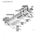
CONTROL (RS 232)
OPTI
CAL FIBER LINK
3-
1
2
12
3
3
Fig.7
Fig.8
Fig.9