


19
English
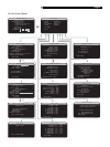
Making Connections
CD Player
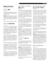
See Figure 7
Connect the left and right analog outputs from
the CD player to the AUDIO IN jacks labeled
CD (left and right).
Optional: Connect the digital output of the
CD player to any of the Optical or Coax digital
inputs on the RSX-1056. Use the INPUT SETUP
screen to assign that digital input to the CD
source.
There are no video connections for a CD Player.
DVD Player
See Figure 9
DVD connections can be made to the VIDEO
1, 2, 3, 4, or 5 inputs. In elaborate systems,
you may wish to use VIDEO 4 or VIDEO 5
for DVD players, since these inputs do not have
corresponding OUTPUT connections. If you
choose VIDEO 1, make sure that you use
VIDEO 1 inputs and outputs for all analog audio
and video connections.
Connect a video cable (Composite Video,
S-Video, and/or Component Video from the
output of the DVD player to the appropriate
VIDEO IN 1–5 input. If you intend to use the
progressive scan feature with an HDTV moni-
tor, you should use Component Video connec-
tions.
Connect the digital output of the DVD player
to any one of the OPTICAL IN or COAXIAL
IN digital inputs on the RSX-1056. Use the
INPUT SETUP screen to assign that digital in-
put to the same video input source used above.
For example, if you use the Video 4 inputs
above, assign the digital input to the VIDEO
4 input.
If you want to record the audio signal from
the DVD player, connect the left and right
analog outputs from the DVD player to the left
and right AUDIO IN jacks corresponding to
the VIDEO IN input selected above.
Cable, Satellite, or HDTV Tuner
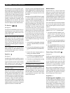
See Figure 5
TV tuner connections can be made to the VIDEO
1, 2, 3, 4, or 5 inputs. In elaborate systems,
you may wish to use VIDEO 4 or VIDEO 5
for TV tuners, since these inputs do not have
corresponding OUTPUT connections. If you
choose VIDEO 1, make sure that you use
VIDEO 1 inputs and outputs for all analog audio
and video connections.
Connect a video cable (Composite Video,
S-Video, and/or Component Video) from the
output of the TV tuner to the appropriate VIDEO
IN 1–5 input. For HDTV signals, you should
use Component Video connections.
Connect the left and right analog outputs from
the TV tuner to the left and right AUDIO IN
jacks corresponding to the VIDEO IN input se-
lected above.
Optional: Connect the digital output of the
TV tuner to any one of the OPTICAL IN or
COAXIAL IN digital inputs on the RSX-1056.
Use the INPUT SETUP screen to assign that
digital input to the same video input source
used above. For example, if you use the Video
4 inputs above, assign the digital input to the
VIDEO 4 input.
Audio Recorder
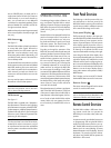
See Figure 8
Connect the left and right analog outputs from
an audio tape deck to the AUDIO IN jacks
labeled TAPE IN (left and right).
Connect the left/right AUDIO OUT/TAPE OUT
jacks to the inputs on the audio tape deck.
Optional: For a digital recording device, con-
nect the digital output of the recorder to one
of the OPTICAL IN or COAXIAL IN digital inputs
on the RSX-1056. Use the INPUT SETUP screen
to assign that digital input to the TAPE source.
If the recording device accepts a digital re-
cording input, connect one of the OPTICAL
OUT or COAXIAL OUT connections to the
digital input of the recorder.
No video connections are required for an audio
recording device.
VCR or Digital Video Recorder
See Figure 6
VCR connections can be made to the VIDEO
1, VIDEO 2, or VIDEO 3 inputs and outputs.
If you choose VIDEO 1, make sure that you
use VIDEO 1 inputs and outputs for all ana-
log audio and video connections.
Connect video cables (Composite Video,
S-Video, and/or Component Video) from the
output of the VCR to the appropriate VIDEO
IN 1–3 input. If you choose S-Video or Com-
ponent Video connections, you should also
make a standard Composite Video connec-
tion so that the TV signals can be displayed
on the RSX-1056 front panel display.
Connect video cables (Composite Video and/
or Component Video) from the VIDEO OUT
jacks to the VCR inputs.
Connect the left and right analog outputs from
the VCR to one pair of the AUDIO IN jacks
labeled VIDEO 1–3.
Connect the left and right AUDIO OUT jacks
for VIDEO 1–3 to the analog inputs on the VCR.
Optional: For a digital recording device, con-
nect the digital output of the recorder to one
of the OPTICAL IN or COAXIAL IN digital inputs
on the RSX-1056. Use the INPUT SETUP screen
to assign that digital input to the VIDEO source
(VIDEO 1, 2, or 3) used for the previous con-
nections. If the recording device accepts a
digital recording input, connect one of the
OPTICAL OUT or COAXIAL OUT connections
to the digital input of the recorder.
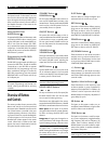
DVD-A or SACD Player
See Figure 10
To hook up a DVD-A, an SACD player, or any
external surround decoder, use audio RCA
cables to connect the outputs of the player to
the RCA jacks labeled MULTI INPUT, making
sure that you observe proper channel consis-
tency, i.e. connect the right front channel to the
R FRONT input, etc. Depending on your sys-
tem configuration, make six connections (FRONT
L & R, SURROUND L & R, CENTER, and SUB-
WOOFER), seven connections (adding a CEN-
TER BACK connection), or eight connections
(adding two CENTER BACK connections).