


SE-DIR800C
48
1234
1234
C
D
F
A
B
E
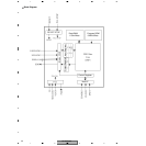
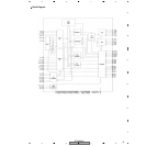
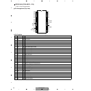
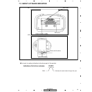
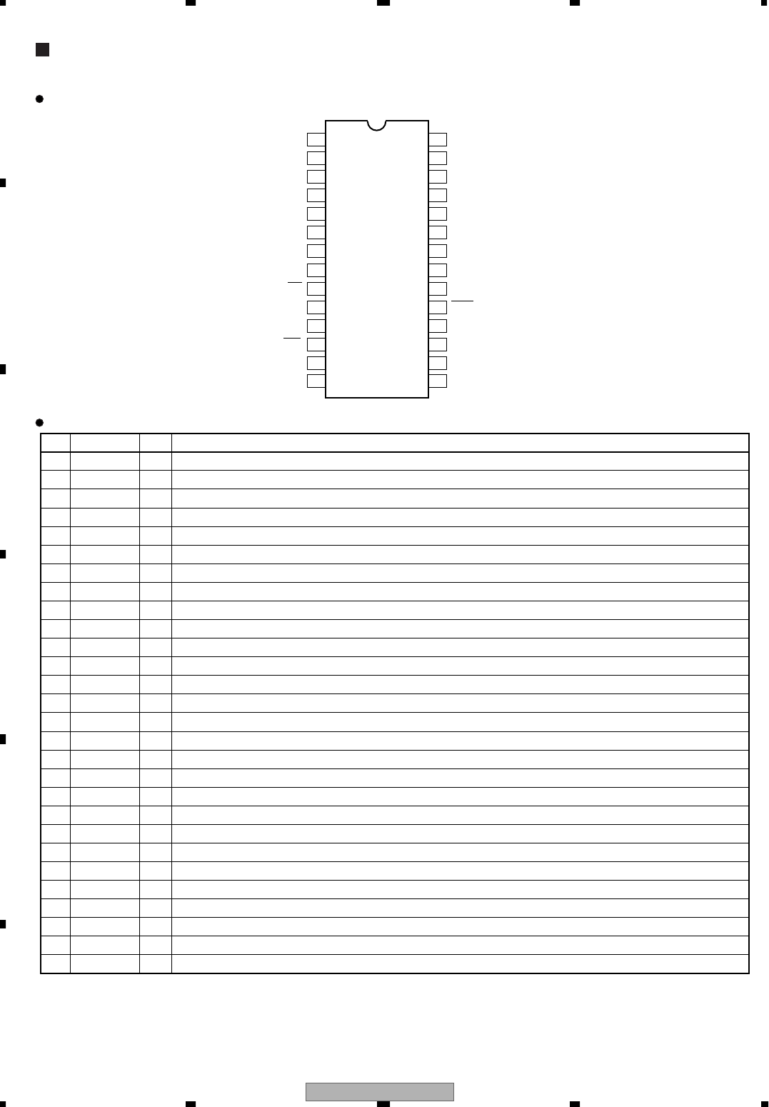
PEF001A9 (PCB ASSY : IC4)
• 8-bit 1-chip microcomputer
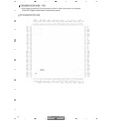
Pin Arrangement (Top view)
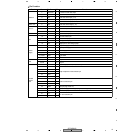
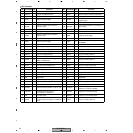
Pin Function
1
PB5
28
PB6
2
PB4
27
PB7
3
PA3
26
PA4
4
PA2
25
PA5
5
PA1
24
PA6
6
PA0
23
PA7
7
PB3
22
OSC2/PG2
8
PB2
21
OSC1/PG1
9
PB1/BZ
20
VDD
10
PB0/BZ
19
RES
11
VSS
18
PC5/TMR1
12
PG0/INT
17
PC4
13
PC0/TMR0
16
PC3
14
PC1
15
PC2
No.
Pin Name
I/O Pin Function
1 PB5 O LED control
2 PB4 O LED control
3 PA3 O LED control
4 PA2 O LED control
5 PA1 O LED control
6 PA0 O LED control
7 PB3 O Chip enable output for DSP
8 PB2 O Chip select output for DSP
9 PB1 O Serial clock output
10 PB0 O Serial data output
11 VSS − Ground
12 PG0 I Serial data input
13 PC0 I Key input 1
14 PC1 I Key input 2
15 PC2 I Key input 3
16 PC3 I Key input 4
17 PC4 I Battery detection input
18 PC5 I Battery voltage abnormality detection
19 RES − External reset input
20 VDD − Power supply
21 OSC1 I CR oscillation input
22 OSC2 O Oscillation output
23 PA7 O LED control
24 PA6 O Charge control
25 PA5 O IR LED control
26 PA4 O A/D reset output
27 PB7 O DSP reset output 1
28 PB6 O DSP reset output 2