


23
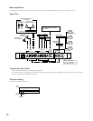
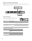
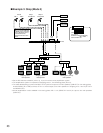
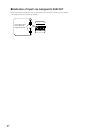
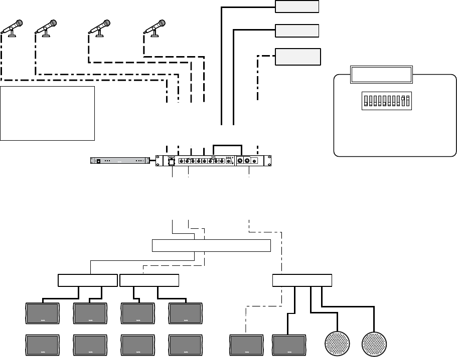
■ Example 3: Shop (Mode 3)
ST OUT L
MONO IN 1
MONO IN 2
MONO IN 3
MONO IN 4
MULTI IN ST
MONO OUT
SUB OUT
ST IN
1 to 4
ON
OFF
4
28
100
1
6
4
28
100
2
6
4
28
100
3
6
4
28
100
4
6
MONO
POWER
4
28
100
1
6
4
28
100
2
6
4
28
100
3
6
4
28
100
4
6
4
4
2
2
8
8
100
100
6
6
ST
MULTI IN
4
28
100
6
SUB OUT
STEREO
MONO
STEREO OUT
INPUT
REAK
LINE IN
SUB
4
2
8
100
6
MONO OUT
Audio Mixer WR-XS3
CD
TAPE
WR-XS3
Cable broad-
casting (BGM)
Shopping zone 1
main speakers
Shopping zone 2
main speakers
Resting place (zone 3)
main speakers
All-call Shop 1
microphone
Shop 2
microphone
Power control unit
Equaliser
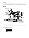
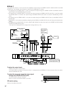
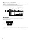
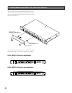
DIP switch setting
When connecting SW BOX
to MONO 2 or 4, announce-
ment in Shopping zones 1,
2 and all-call can be
performed with one micro-
phone.
Unit mode: 3
SUB OUT: Cable broadcasting,
Mic 1, Mic 2
Internal switch: ON
Power amplifier Power amplifier Power amplifier
Mic 1 Mic 2
•Set the DIP switches to Mode 3 (refer to p. 17) to form a three-zone amplification system.
• The amplification system is composed of Shopping zones 1, 2 and Resting place (Zone 3).
• The cable broadcasting connects the MULTI IN ST jacks and output to the main speakers (SUB OUT) in the resting place.
Another BGM (CD or TAPE) connects ST IN 1 to 4 and output to the main speakers in Shopping zone 1 and 2 (ST OUT L
and MONO OUT).
• All-call amplification is also available in the resting place. Mic 1 or 2 (MONO IN 1 and 2) is output to the main speakers
(SUB OUT).