


22
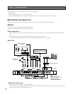
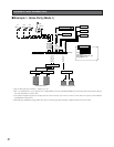
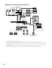
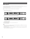
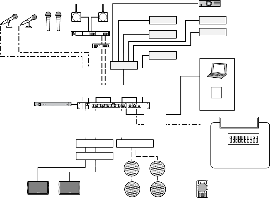
■ Example 2: Presentation Room (Mode 2)
MONO IN 1
REC OUT
MONO IN 2
MONO IN
3 to 4
ST IN
1 to 4
LINE IN
SUB OUT
MONO OUT
ST OUT L
ST OUT R
ON
OFF
4
28
100
1
6
4
28
100
2
6
4
28
100
3
6
4
28
100
4
6
MONO
POWER
4
28
100
1
6
4
28
100
2
6
4
28
100
3
6
4
28
100
4
6
4
4
2
2
8
8
100
100
6
6
ST
MULTI IN
4
28
100
6
SUB OUT
STEREO
MONO
STEREO OUT
INPUT
REAK
LINE IN
SUB
4
2
8
100
6
MONO OUT
Audio Mixer WR-XS3
Ceiling speakers
DVD/CD
MD
TAPE
VTR
TAPE(REC)
WR-XS3
Projector
Note PC
Portable MD
Antenna for
wireless microphone
Wireless
microphone
Mic 1 Mic 2
Diversity wireless receiver
Howling suppressor
[Your sources]
Main speakers
AV switcher
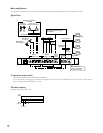
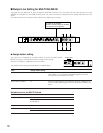
DIP switch setting
Foldback powered loudspeaker
(For Mic 1 and 2)
Power control unit
Equaliser
Power amplifier
Power amplifier
Unit mode: 2
Sub output:MONO IN 1
and 2
•Set the DIP switches to Mode 2. (Refer to p. 16.).
• This connection raises the howling margin. BGM (ST IN) is output through ST OUT L/R to the main speakers.
Sounds from microphones (MONO IN 1 and 2) and wireless microphones (MONO IN 3 and 4) are output to ceiling speak-
ers (MONO OUT).
• Your presentation sources can be input from the front panel's LINE IN to be mixed through an AV switcher (ST IN 1 to 4).
• Sounds from Mic 1 and 2 (MONO IN 1 and 2) can be output to the foldback loudspeaker (SUB OUT).