


17
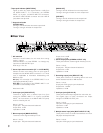
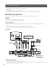
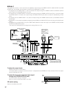
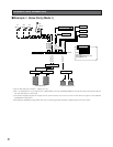
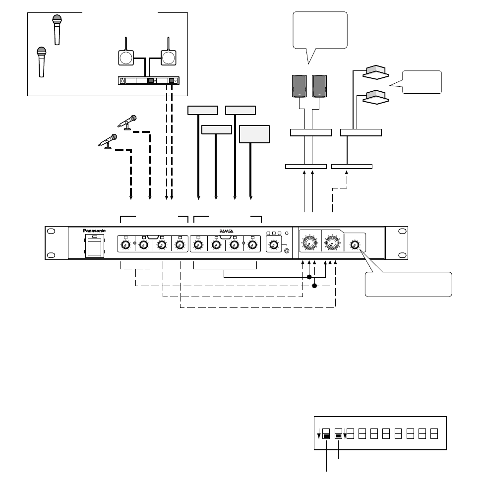
● Mode 3
The signals from stereo or mono input lines are separately output through the STEREO OUTPUT, MONO OUTPUT and SUB
OUTPUT jack. For example, this connection is used for zone amplification in a shop.
• The signals from the MONO INPUT 1 and 2 connectors are output through the STEREO OUTPUT and MONO OUTPUT
jacks. (Input for all-call broadcasting in any zone)
• The signals from the MONO INPUT 3 connector are output through the STEREO OUTPUT jack (Zone 1) and the signals
from MONO INPUT 4 connector are output through the MONO OUTPUT jack (Zone 2). (Input for broadcasting in each
zone)
• The signals from the STEREO INPUT 1 to 4 jacks are output through the STEREO OUTPUT (Zone 1) and MONO OUTPUT
(Zone 2) jack.
• Amplification in other areas is possible by assigning another BGM to the SUB OUTPUT jack and mixing with all-call broad-
casting.
• The signals from the MULTI INPUT ST jack or MULTI INPUT MONO connector are output to the STEREO OUTPUT, MONO
OUTPUT and SUB OUTPUT jacks.*
*The output line is assigned with the assign button setting. (Refer to p. 19.)
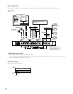
To adjust the output levels
Requires setting of an internal switch.
In the case shown in the figure, the volume of Zone 1 is adjusted with the STEREO OUT knob ,and that of Zone 2 is adjust-
ed with the MONO OUT knob.
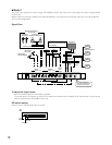
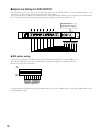
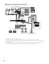
To output the mono mix signal (the same signal
through the STEREO OUTPUT jack)
The internal switch setting is necessary.
Refer to a service manual procurable in your area.
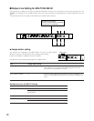
DIP switch setting
Switches A and B are set to OFF.
Mono output is
also available
in Zone 1.
(Switch inside)
Zone 2
Zone 1 Zone 2
Wireless
microphone
Wireless
microphone
MD
CD TAPE
MONO
INPUT 1 to 4
STEREO
INPUT 1 to 4
MONO
1 to 2
(Zone 1 and 2)
MONO3
(Zone 1)
MONO4 (Zone 2)
Digital Multi
Equalizer
Power
amplifier
Speakers
Video
sound
Microphone
on the platform
Microphone
for a host
Antenna for
wireless microphone
Diversity wireless receiver
Wireless microphone
in the hall
4
28
100
1
6
4
28
100
2
6
4
28
100
3
6
4
28
100
4
6
MONO
POWER
4
28
100
1
6
4
28
100
2
6
4
28
100
3
6
4
28
100
4
6
4
4
2
2
8
8
100
100
6
6
ST
MULTI IN
4
28
100
6
SUB OUT
STEREO
MONO
STEREO OUT
INPUT
REAK
LINE IN
SUB
4
2
8
100
6
MONO OUT
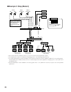
Audio Mixer WR-XS3
Any mono and stereo input
can be assigned to the SUB
OUTPUT jack as Zone 3
ON
OFF
Switch A
Switch B