


7
Getting to Know the T-4555—Continued
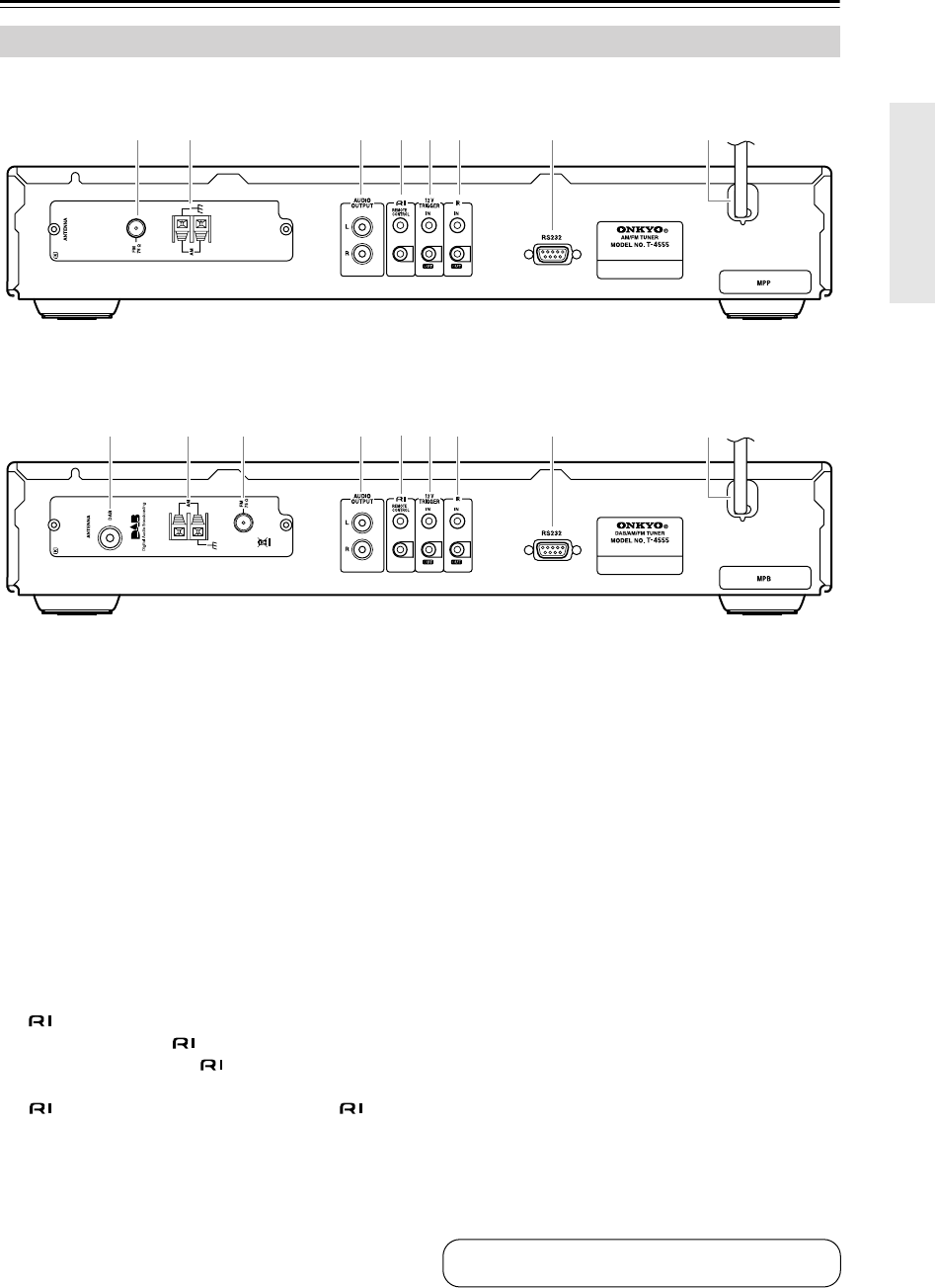
■ European Model
Comes with C-AMFM tuner board installed.
■ U.K. Model
Comes with C-DAB tuner board installed.
For detailed information, refer to the pages in parentheses.
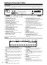
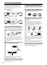
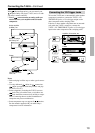
A DAB ANTENNA (C-DAB tuner board only)
(11)
This jack is for connecting the supplied DAB
antenna.
B AM ANTENNA (10)
These push terminals are for connecting the sup-
plied AM loop antenna or an outdoor AM antenna.
C FM 75Ω ANTENNA (10)
This jack is for connecting the supplied indoor FM
antenna or an outdoor FM antenna.
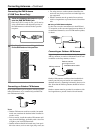
D AUDIO OUTPUT (12)
Using the supplied audio cable, connect these out-
put jacks to an analog audio input on your amp.
E REMOTE CONTROL (13)
These two identical (Remote Interactive) jacks
can be connected to the jacks on your other
Onkyo components for interactive control. To use
, the T-4555 must be connected with an
cable and an audio cable.
F 12V TRIGGER IN/OUT (13)
The 12V TRIGGER IN jack can be connected to the
12-volt trigger output on another component, so that
when the other component is turned on, the T-4555
turns on as well.
The 12V TRIGGER OUT jack can be connected to
the 12-volt trigger input on another component, so
that when the T-4555 is turned on, the other compo-
nent turns on as well.
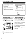
G IR IN/OUT (14)
A commercially available IR receiver can be con-
nected to the IR IN jack, allowing you to control the
T-4555 while you’re in another room, or control it
when it’s out of sight, for example, installed in a
cabinet.
A commercially available IR emitter can be con-
nected to the IR OUT jack to pass IR (infrared)
remote control signals through to other components.
H RS232
This port is for connecting the T-4555 to home
automation equipment and external controllers.
I Power cord (15)
The power cord should be connected to a suitable
wall outlet.
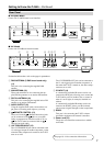
Rear Panel
32 4567 8 9
9
1234
5
67 8
See pages 10–14 for connection information.