


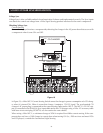

Light Sensing
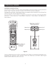
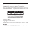
Using a light sensor (LS-1) to synchronize your components is usually your last choice, simply because the other
choices are more reliable. The Niles LS-1 Light Sensor can synchronize a component by sensing changes in light.
The 12V output of the LS-1 is then connected to the ZR-4630’s Sync Input dedicated for that component, a mini-
plug to RCA adapter is required for this connection (see Connections for more information).
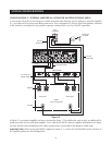
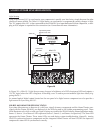
In Figure 20, a Niles LS-1 Light Sensor senses changes in brightness of a DSS’s front panel LED and outputs a
12V DC signal when the LED is brightest. A blocking cover is used to prevent ambient light from falsely trig-
gering the LS-1.
An unused optical digital output located on the rear panel of a digital source component can also provide a
light source for Sync using the LS-1.
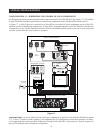
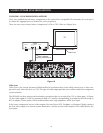
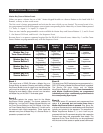
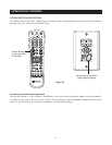
SOURCE AND HOME THEATER SYNC STATUS
Sync status (the presence or absence of a valid sync signal) of source components and the Home Theater asso-
ciated with the Master ZR-4630 are displayed on the LEDs located in the hidden programming panel. These
LEDs illuminate only while a valid sync signal is being received by the ZR-4630 during normal operation mode.
Source 2, Source 3, and Source 4 LEDs represent Source 2, Source 3, and Source 4 respectively. The Tuner LED
represents the Home Theater. These status LEDs are used during system troubleshooting. Manually turning
ON/OFF synchronized source components and the integrated Home Theater will turn ON/OFF the respective
component’s status LED if synchronized correctly.
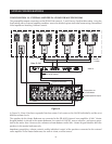
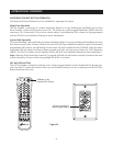
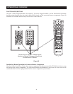
SOURCE POWER SYNCHRONIZATION
31
Unswitched
AC Outlet
Power Supply
Niles LS-1
DSS
Light Sensing Probe
placed over an LED
Audio Out
Figure 20