Chapter 2 Connecting Signals
NI PXI-4224 User Manual 2-12 ni.com
Ground-Referenced Signal Connection
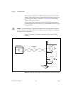
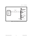
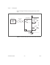
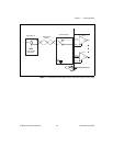
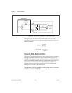
Figures 2-3, 2-5, 2-7, and 2-9 illustrate the ground-referenced signal
connection. In this configuration, the voltage source being measured is
referenced to its own ground reference that is connected through a
conductive path to the instrument ground reference. For example, the path
can be through a common earth ground or through the power line ground.
To connect a ground-reference signal source to the NI PXI-4224, the signal
(V
SIG
+) is connected to the NI PXI-4224 channel (AI X +). The signal
reference (V
SIG
–) is connected to the channel reference (AI X –).
Shielded Ground-Referenced Signal Connection
(Recommended)
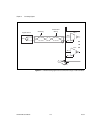
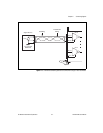
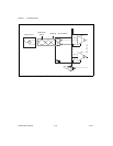
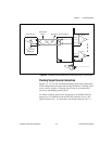
Figures 2-5 and 2-9 illustrate shielded ground-referenced signal
connections. The connection to this signal source is identical to the
ground-referenced signal connection with the addition of shielding
around the field wiring. The shielding is grounded at the signal source
ground (V
SIG
Ground Reference). Connect the signal (V
SIG
+) to the
NI PXI-4224 channel (AI X +). Connect the signal reference (V
SIG
–) to the
channel reference (AI X –).
This shielding scheme is effective at reducing capacitive or electrically
coupled noise. The same concerns regarding the difference in ground
potentials, discussed in the Ground-Referenced Signal Connection section,
also apply to this configuration.
For more information about the function of the NI PXI-4224 and other
measurement considerations, refer to Chapter 4, Theory of Operation.


