32
CHAPTER 7
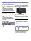
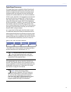
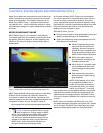
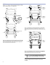
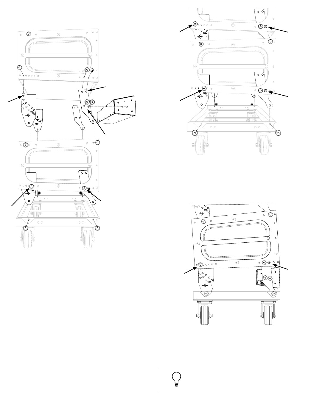
Figures 7.8, 7.9 and 7.10 show example transport configu-
rations using the MILO 120 AlignaLinks.
Figure 7.8. Configuration for transporting cabinets on the MCF-MILO
caster frame leaving the MILO 120-I in between cabinets; in this case,
there are 6 degrees between cabinets and a splay of 0 degrees be-
tween the last cabinet and the caster frame.
Figure 7.9. Configuration for transporting cabinets on the MCF-MILO
caster frame using the MILO 120 AlignaLinks to achieve a splay of 0
degrees between cabinets and between the last cabinet and the caster
frame.
Figure 7.10. Configuration for transporting cabinets on the MCF-MILO
caster frame leaving the MILO 120-I; in this case, there is a splay of 4
degrees between the last cabinet and the caster frame.
TIP: You can also transport the MG-3D/M at-
tached to the top MILO/MILO 120 on a stack.
A range of rugged protective transport covers is also
available.
T 0
Bottom
(transport)
position
T 6
Top (rigging)
position
Bottom (insert/
transport)
position
Bottom (transport)
position
17 / MCF
Bottom
(transport)
position
17 / MCF
T 6
Top
(rigging)
position


