31
CHAPTER 7
MG-3D/M MULTIPURPOSE GRID
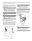
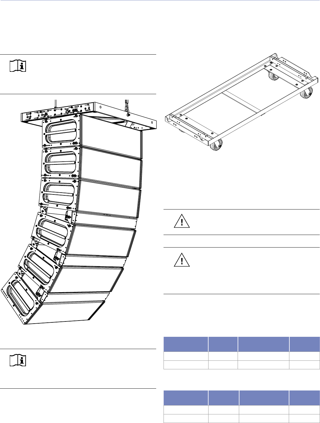
The MG-3D/M multipurpose grid supports flying and ground
stacking multiple MILO/MILO 120 loudspeakers and/or M3D
line array loudspeakers (or M3D-Subs) in numerous configu-
rations (Figure 7.6).
NOTE: The MLK-MILO link kit is required
when using the grid with MILO or MILO 120
loudspeakers, and the MLK-3D is required for M3D
and M3D-Sub loudspeakers.
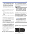
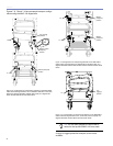
Figure 7.6. MG-3D/M multipurpose grid supporting a MILO (top three
cabinets)/MILO 120 (bottom three) curvilinear array
NOTE: For information on load ratings and
how to set up the MG-3D/M, please use the
MG-3D/M Multipurpose Grid and Accessories As-
sembly Guide available at www.meyersound.com.
Because rigging connections are rigid, the array tilt is easy
to adjust – often eliminating the need for a pullback strap
in flown configurations. If circumstances dictate an acute
array curve, then a PBF-MILO pull back frame can be at-
tached to the lowest cabinet.
MCF-MILO CASTER FRAME
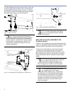
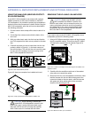
The MCF-MILO caster frame (Figure 7.7) allows you to
transport stacks of up to four MILO/MILO 120 cabinets, us-
ing the MILO 120 AlignaLinks to secure the cabinets to the
caster frame.
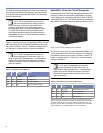
Figure 7.7. MCF-MILO caster frame
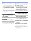
Whether you’re deploying or striking a MILO/MILO 120
array, the MCF-MILO caster frame can support the entire
weight of the array — making it easy to assemble or dis-
semble. The rigid frame also facilitates the use of forklifts.
CAUTION: Do not exceed four cabinets high
on a block to avoid tipping over the stack.
CAUTION: When lifting a block with a forklift,
always keep the forks wide – close to the
MCF-MILO caster frame’s wheels. Doing otherwise
(for example, moving the forks together in the
center) may bend the frame.
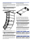
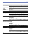
The versatility of the MILO 120 AlignaLinks allows for sev-
eral configurations when transporting stacks of MILO/MILO
120 cabinets. Tables 7.1 and 7.2 show the most common.
Table 7.1: MILO/MILO 120 connection to another cabinet
Front Link
Position
Rear Link
Position
Angle Between
Cabinets
MILO 120-I
Insert
Bottom (transport) T 0 0 Degrees No
Top (rigging) T 6 6 Degrees Optional
Table 7.2: MILO/MILO 120 connection to MCF-MILO caster frame
Front Link
Position
Rear Link
Position
Angle Between
Cabinet and Frame
MILO 120-I
Insert
Bottom (transport) 17 / MCF 0 Degrees No
Top (rigging) T 6 4 Degrees Optional


