13
CHAPTER 3
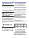
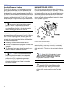
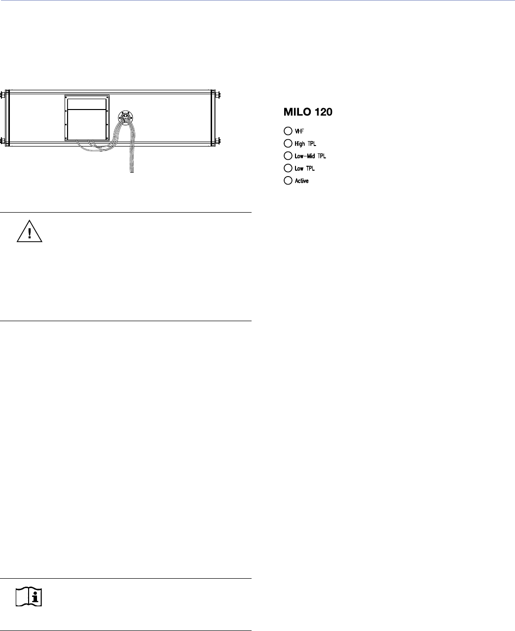
To utilize the strain relief fitting, insert the signal, data, and
AC connections into each loudspeaker as the array is being
rigged (swag all cables under the optional rain hood’s side
flaps if installed), and tie the cables off to the ring/stud fit-
ting, as shown in Figure 3.3.
Figure 3.3. Cables are easily tied off using the rear ring/stud fitting
(figure shows optional rain hood installed).
CAUTION: The strain relief stud fitting must
be used only to secure system cabling. This
fitting is not intended to be used with system rigging
or a pull-back motor (pulling the bottom of the array
backward to increase downward tilt). The point is
mounted to the side of the amplifier area so as not
to interfere with the optional rain hood (if fitted) and
the amplifier fan exhaust area.
THE TRUPOWER® LIMITING SYSTEM
Conventional limiters assume a constant loudspeaker
impedance and therefore set the limiting threshold by
measuring voltage only. However, this method is inaccurate
because the loudspeaker’s impedance varies throughout
its frequency range, changing in response to the frequency
content of the audio source. In addition, the impedance also
changes due to temperature variations in the voice coil and
magnet. Consequently, conventional limiters begin limiting
prematurely, which under-utilizes system headroom and
lessens the loudspeaker’s dynamic range.
In contrast, TruPower limiting accounts for varying loud-
speaker impedance by measuring current as well as voltage
to compute the actual power dissipation in the voice coil.
TruPower limiting improves performance before and during
limiting by allowing each driver to produce maximum SPL
across its entire frequency range.
NOTE: TruPower limiting only reduces the
signal level to keep the voice coil below 180
degrees Celsius, hence the peaks are unaffected.
In addition, TruPower limiting eliminates power compression
when the system is operated at high levels for extended
periods, and also extends the driver life cycle by controlling
voice coil temperatures.
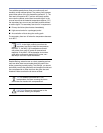
The actual power is monitored for three of MILO 120’s four
amplifier channels. When the safe continuous power level
is exceeded, the TruPower limiter controlling that amplifier
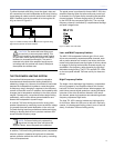
channel engages. TruPower limiting activity is indicated
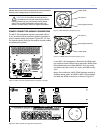
by the LEDs on the user panel (Figure 3.4). The very-high
frequency channel is controlled by a sophisticated average
and peak voltage limiter.
Figure 3.4. MILO 120 Limit LEDs
Low- and Mid-Frequency Limiters
The MILO 120 loudspeaker’s left and right 12-inch cone
drivers are powered by separate amplifier channels, each
with a power detector but routed to one limiter; the limiter
tracks both channels and uses the higher of the two values
to engage. By limiting both amplifier channels equally, any
anomalies in the frequency range shared by the drivers is
eliminated during limiting. The LO TPL and MID TPL LEDs
on the user panel indicate TruPower activity for these two
drivers.
High-Frequency Limiter
The single 4-inch diaphragm high-frequency compression
driver is powered by one amplifier channel; this channel
has both TruPower and peak limiters. When engaged, the
peak limiter prevents signal peaks from causing excessive
excursion in the driver as well as distortion in the ampli-
fier channel, preserving headroom and maintaining smooth
frequency response at high levels.
The High TPL LED is used to indicate any limiting activity
for this driver. When the LED turns on and off in rapid suc-
cession, it indicates peak limiting; when it turns on and off
slowly, it indicates TruPower limiting activity.


