29
CHAPTER 7
MILO 120 features Meyer Sound’s QuickFly rigging system
with rugged, reliable and simple components. QuickFly
facilitates flying or ground stacking MILO 120 loudspeakers
in a variety of applications.
CAUTION: All Meyer Sound products must
be used in accordance with local, state, fed-
eral and industry regulations. It is the owner’s and/or
user’s responsibility to evaluate the reliability of any
rigging method for their application. Rigging should
be carried out only by experienced professionals.
CAUTION: Always use properly rated rigging
hardware.
CAUTION: It is important to inspect rigging
hardware regularly and replace worn or dam-
aged components immediately.
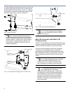
MILO 120 CUSTOM ALIGNALINKS
MILO 120 loudspeakers are designed to be rigged using the
same QuickFly accessories as the MILO standard model,
including the MG-3D/M multipurpose grid and MCF-MILO
caster frame. The MILO 120’s custom front and rear Alig-
naLinks at the cabinet corners couple the units for either
flying, stacking or transporting allowing multiple positions.
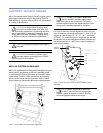
Figure 7.1. Custom MILO 120 front and rear AlignaLinks
NOTE: The MILO 120 custom AlignaLinks
attach to the MILO standard rigging frame.
When setting the angles for the MILO 120, use the
numbers engraved on the rear AlignaLinks as a guide,
and ignore the numbers engraved on the frame.
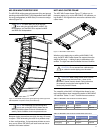
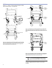
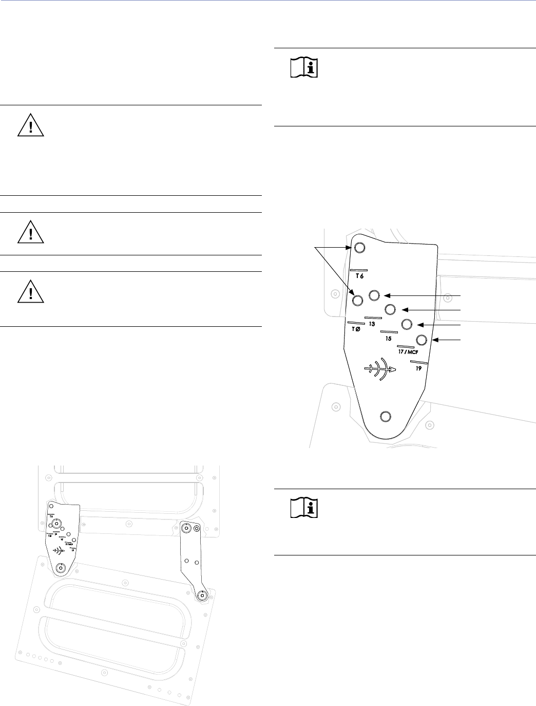
For flying or stacking, the rear AlignaLinks allow four posi-
tions for optimum acoustical performance — from 13 to 19
degrees of cabinet splay (13°, 15°, 17°, 19°) — as shown
in Figure 7.2. In addition to the four angle settings, the rear
AlignaLinks include two dedicated transport positions and
one shared position (17 / MCF) that is used for setting an
angle or for transport.
Figure 7.2. Splay angle and transport settings on the MILO 120 rear
AlignaLinks
NOTE: Optimal acoustical performance
for MILO 120 is achieved by using angles
between 13 and 19 degrees in a MILO 120 array;
avoid using angles outside of this range.
CHAPTER 7: QUICKFLY RIGGING
Transport
positions
13°
15°
17°
19°


