22
CHAPTER 5
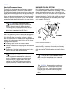
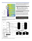
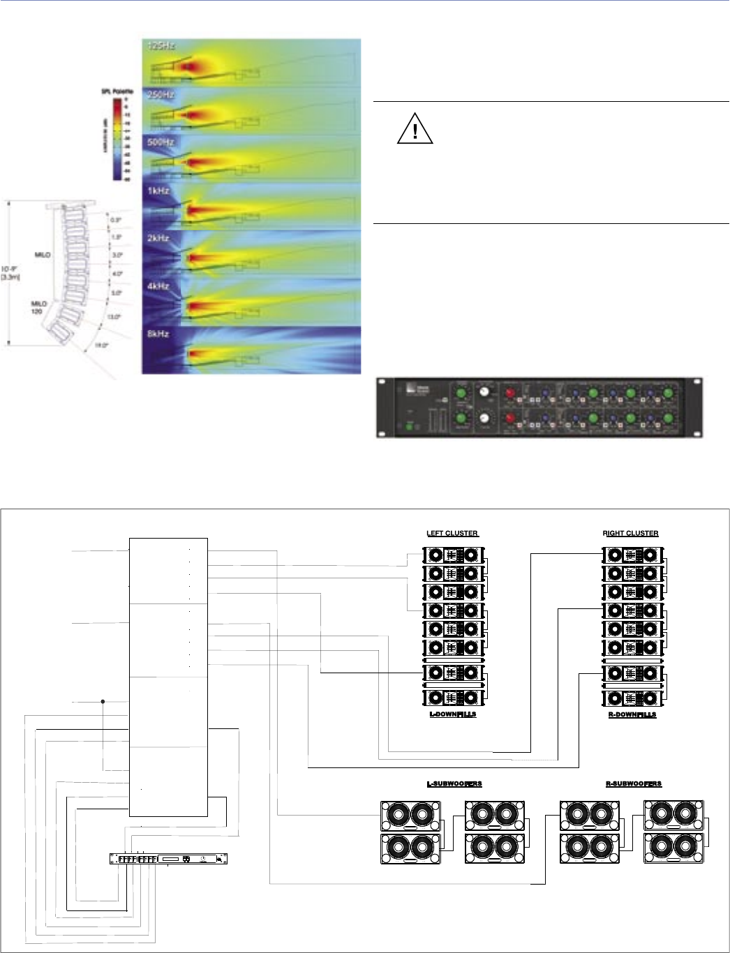
Figure 5.1. MAPP Online plots on the right illustrate the vertical directiv-
ity characteristics of the array on the left, with a section view of the
venue superimposed.
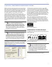
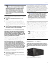
The block diagram (Figure 5.2) shows one method of driving
this example array, along with subwoofers (not in the MAPP
Online predictions).
Equalizers for each zone, as well as digital delays, provide
frequency and time adjustment to compensate for the vari-
ous sub-systems if they are geometrically out of plane. For
example, fl own array and ground-stacked subs.
CAUTION: This example is not meant to
be used as a template for your own system
designs. Acoustical characteristics, physical con-
straints, audio content, audience, and other relevant
factors should always be uniquely weighed into your
own applications on a per-project basis.
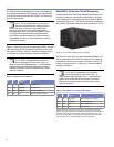
LD-3 Compensating Line Driver
In addition to its unique atmospheric correction for high
frequencies and low-frequency compensation capabili-
ties, Meyer Sound’s LD-3 air attenuation compensating
line driver (Figure 5.3) can be used effectively to integrate
subwoofers in a design with MILO/MILO 120 arrays.
Figure 5.3. The LD-3 compensating line driver
Figure 5.2. Sample block diagram of MILO, MILO 120, 700-HP system
Digital Delay
2 In x 6 Out
Digital Delay/EQ
LD-3
Channel A
IN SUB OUT
CH 1 OUT
CH 2 OUT
CH 3 OUT
Channel B
IN SUB OUT
CH 1 OUT
CH 2 OUT
CH 3 OUT
Channel A
INSERTS SENDS
IN SUB OUT
Full Range
IN CH 1 OUT
Post Array
IN CH 2 OUT
Post Array
IN CH 3
Post HPF
Channel B
INSERTS SENDS
IN SUB OUT
Full Range
IN CH 1 OUT
Post Array
IN CH 2 OUT
Post Array
IN CH 3
Post HPF
(6) MILO
(6) MILO
(2) MILO 120 (2) MILO 120
W/ MILO 120-I INSERTS
(OPTIONAL)
W/ MILO 120-I INSERTS
(OPTIONAL)
(4) 700-HP SUB
(4) 700-HP SUB


