37
Front
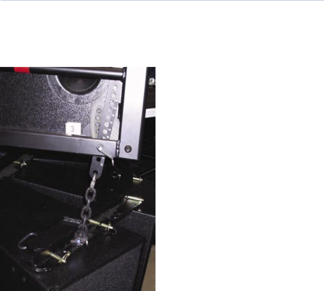
1. Raise the M3D array to give sufcient space to slide
the front (long) adjustable link plate up (vertically) in
between the MRF-3D Rigging Frame and the CamLink,
and use the same hole that is used to adjust the
CamLink (see Figure 46).
Figure 46. Pinning front adjustable link plate
2. Remove the QRP holding the CamLink in place. The
CamLink should swing down freely.
3. Slide the adjustable link plate up between the CamLink
and MRF-3D, aligning the weldment hole with the
appropriate hole in the adjustable link plate. The setting
should result in a net (relative to the bottom M3D)
downtilt of 5˚ (i.e., if the rear hole is pinned at 2˚, then
the front hole will be pinned at 7˚).
4. Insert the QRP through the MRF-3D hole just far
enough in to temporarily hold the adjustable link plate in
place.
5. Rotate the CamLink back up again, and then fully insert
the QRP through the CamLink and through the opposite
side of the MRF-3D. Make sure the pin is seated all the
way in and locked into place.
6. Place the bottom link of the chain in between the two
vertical anges on the front arm.
7. Align the link with the holes in the anges and insert a
QRP through one ange, through the link, and through
the other ange. Make sure the pin is seated all the way
in and locked into place.
