10
11
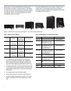
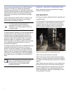
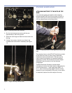
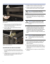
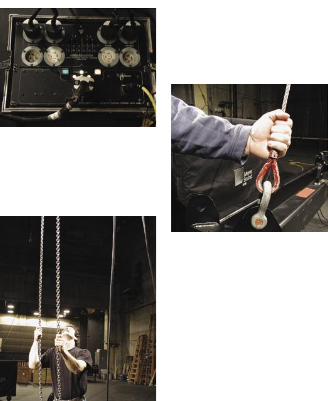
Figure 10. Checking phase (chain direction)
4. Run the chain through the motors until they are
approximately 2 feet off the ground.
5. Attach the chain bags and feed the unused chain into
the bag.
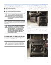
6. If using 2-ton motors, check for any twists in the
overhead chain and correct if necessary (see Figure
11).
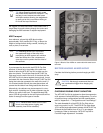
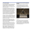
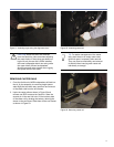
Figure 11. Rigger checking overhead chain
STACKING AN M3D ARRAY
ATTACHING MOTORS TO THE MTG-3D TOP
GRID
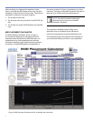
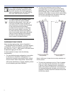
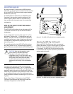
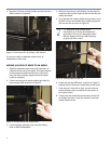
Use rated steel cables and shackles when attaching
motors to the MTG-3D Top Grid, as shown in Figure 12.
The MTG-3D Top Grid will accommodate 5/8-inch and
3/4-inch shackle sizes on its pickup points.
Figure 12. Attaching motors or bridle legs to the MTG-3D Top
Grid
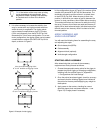
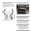
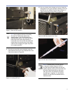
The extension frame on the MTG-3D Top Grid is provided
to help keep the center of gravity evenly distributed
between the front and back points. This frame can be
used in either the retracted or the extended positions,
depending on which will provide the most even weight
distribution when the array is in its nal trimmed
conguration.
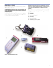
The M3D Placement Calculator provides weight
information on the front and back loads to help select the
correct pickup lotions — back rigging point (BRP) 1, 2,
or 3 — prior to the array being rigged. However, during
assembly it may be necessary for the front or rear motors
to temporarily support the entire weight of the array.


