10
11
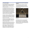
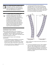
The allowable system center of gravity range must be
within the front rigging point and one of the pickup
choices provided, as illustrated in Figure 34 on page 26.
BRP 1 from the main frame
BRP 2 from the extension frame retracted
BRP 3 from the extension frame extended
CAUTION: An array in which the center of
gravity falls outside the allowable range of
the MTG-3D Top Grid, once it is in its nal
trimmed position, is unstable and therefore
unacceptable!
!
Refer to “Appendix A — Congurations and Load Ratings”
for allowable weights, bridle lengths, and number of M3D
loudspeakers.
CAUTION: Always use properly rated rigging
shackles, chain, and hardware to attach the
motors to the MTG-3D Top Grid. Be sure that
the motors, hardware, and rigging points are
sized appropriately for the entire weight of
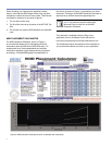
the array. The M3D Placement Calculator can
help in determining the load of the system
you are planning to hang.
!
ATTACHING M3DS TO THE MTG-3D TOP GRID
Use properly rated hardware to attach the rigging steel
and motors to the MTG-3D Top Grid.
CAUTION: Everyone involved in assembling
an array should be coached not to place their
hands between the cabinets and the frames.
!
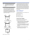
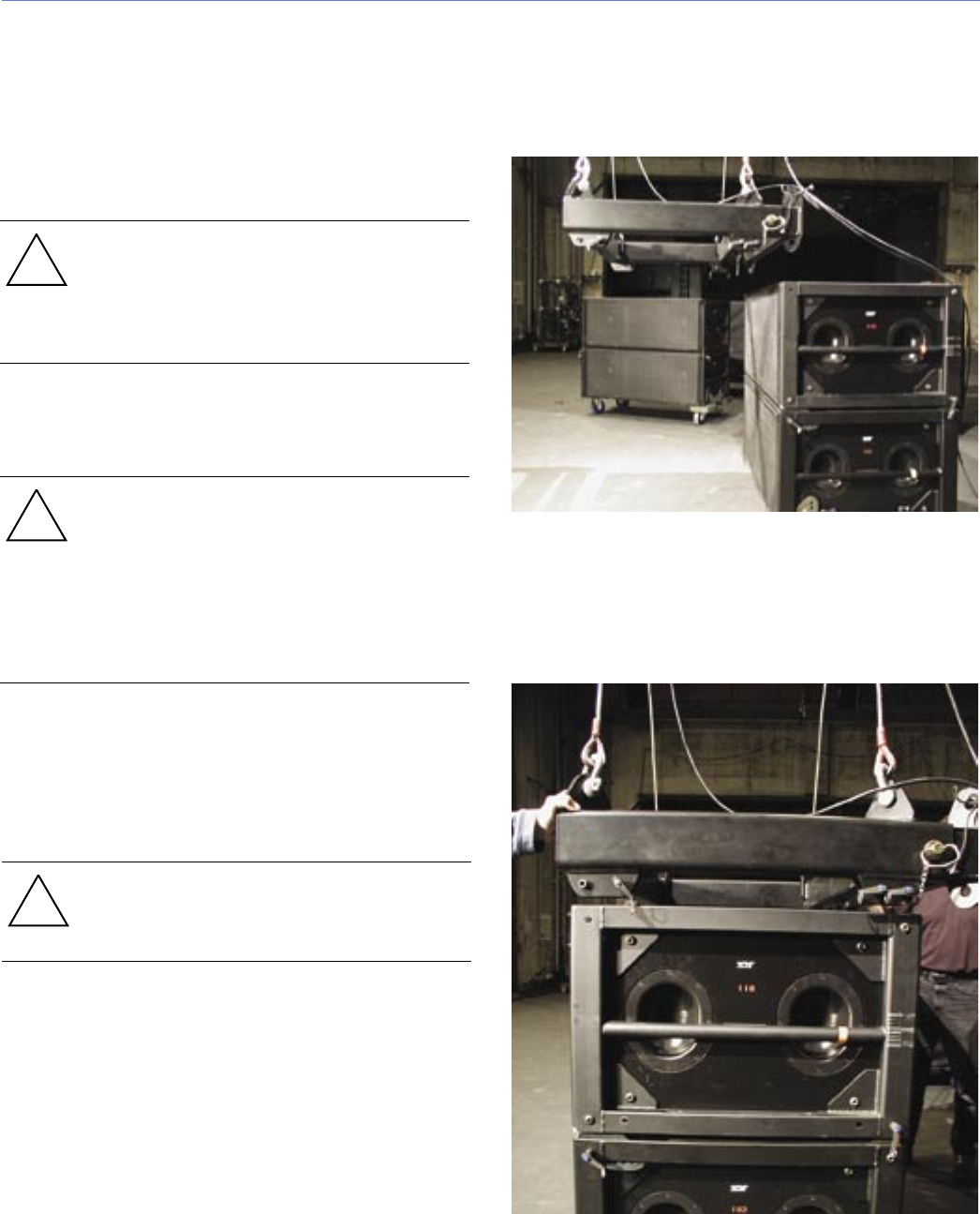
1. Once the motors are attached to the MTG-3D Top
Grid, raise the MTG-3D Top Grid, as shown in Figure
13, to the necessary working height in preparation for
attaching the rst block of M3Ds. Adjust the MTG-3D
Top Grid to be parallel with the top M3D of the block.
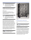
Figure 13. The MTG-3D Top Grid raised for pick up of the rst
M3D block
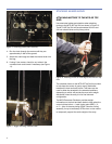
2. Carefully lower the MTG-3D Top Grid, positioning it
just over the top M3D in the block, as shown in Figure
14.
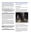
Figure 14. The MTG-3D Top Grid positioned over the rst
M3D block


