16
17
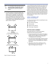
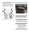
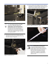
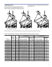
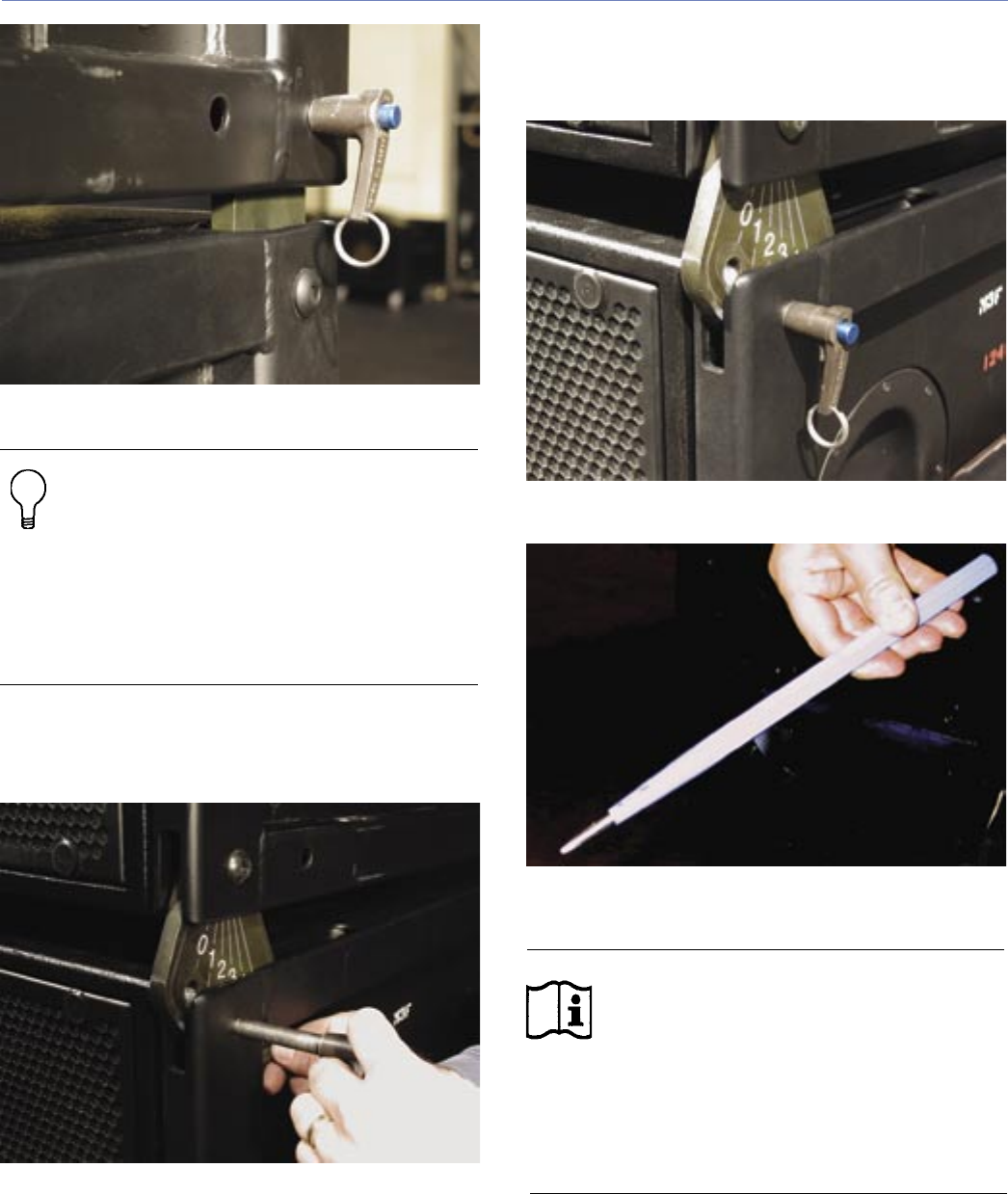
Figure 27. Rear link QRP inserted
TIP: Here is another technique for setting
the rear link. Position the upper array
approximately 1 inch (25 mm) above the
waiting cabinet block. Push the own array
behind the lower block approximately 2
inches (50 mm). Fold out the rear link(s) and
rotate them into the end frame of the upper
cabinet while swinging the upper array back
to its original position..
9. Once the two rear links are connected, unpin the
CamLinks and set the pin to the desired hole in the
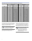
CamLink as shown in Figure 28.
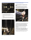
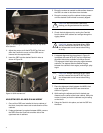
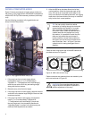
Figure 28. Inserting QRP at 3˚
10. Use up or down motor bumps to pivot (or hinge) the
lower block to the upper cabinets, allowing you to set
the QRP into the desired CamLink hole as shown in
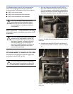
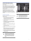
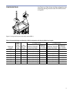
Figure 28 and secure it as shown in Figure 29.
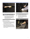
Figure 29. QRP fully inserted into 3˚ hole
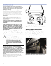
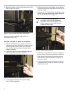
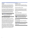
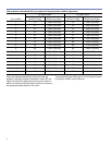
Figure 30. 0.25" (6.35 mm) drift punch
NOTE: If cabinets are on uneven ground
or aligned at a slight diagonal, the front
and rear CamLink/frame holes may be only
partially aligned. Insert a 0.25-inch (6.35 mm)
drift punch (see Figure 30) into the frame
hole, and “lever” the CamLink into place
by pushing or “wiggling” it in the desired
direction. A drift punch is available from a
hardware store.


