22
23
CONFIGURATION B
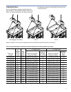
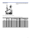
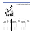
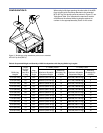
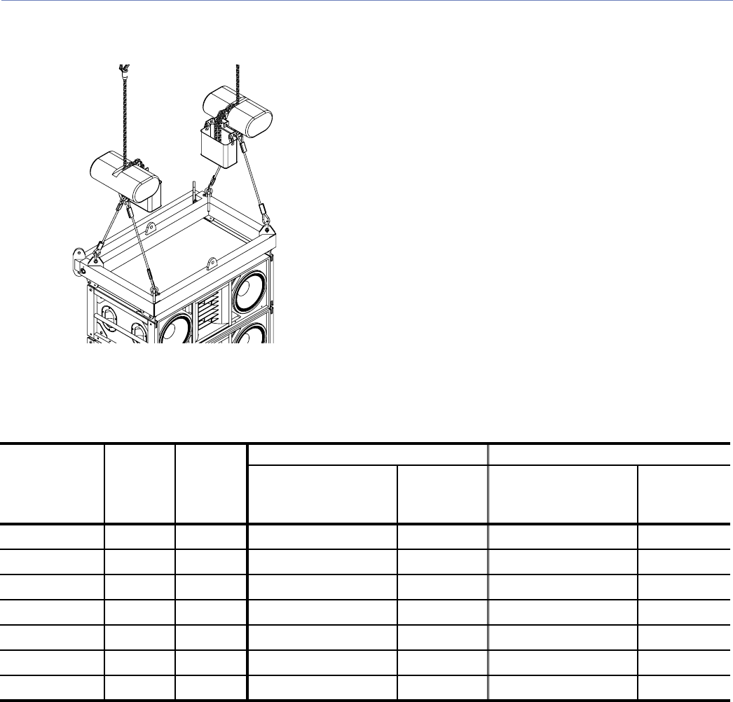
Figure 35. Using bridle leg short side pickup points (BRP 1)
Use Table 5 and Table 6 when the lifting conguration uses
bridle legs spanning the short sides of the M3D as shown
in Figure 35.
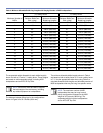
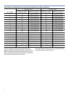
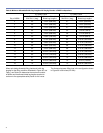
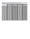
Table 5: Suspended Weight and Quantity of M3D Loudspeakers with Varying Bridle Leg Lengths
Bridle Leg
Lengths
Angle
Between
Bridle
and Grid
α (deg)
Max
Top Grid
Angle
5:1 Safety Factor 7:1 Safety Factor
Maximum Allowable
Suspended Weight
Maximum
Allowable
Qty. of M3Ds
Maximum Allowable
Suspended Weight
Maximum
Allowable
Qty. of M3Ds
2.0 ft. (610 mm) 51˚ ±25˚ 3317 lbs (1504.57 kg) 7 2369 lbs (1074.56 kg) 5
2.5 ft. (760 mm) 60˚ ±25˚ 4570 lbs (2072.92 kg) 10 3265 lbs (1480.98 kg) 7
3.0 ft. (910 mm) 66˚ ±25˚ 5742 lbs (2604.53 kg) 13 4101 lbs (1860.18 kg) 9
3.5 ft. (1070 mm) 68˚ ±25˚ 6874 lbs (3117.99 kg) 15 4910 lbs (2227.14 kg) 11
4.0 ft. (1220 mm) 72˚ ±25˚ 7983 lbs (3621.03 kg) 16 5702 lbs (2586.38 kg) 13
4.5 ft. (1370 mm) 74˚ ±25˚ 7983 lbs (3621.03 kg) 16 6484 lbs (2941.09 kg) 15
5.0 ft. (1520 mm) 76˚ ±25˚ 7983 lbs (3621.03 kg) 16 7258 lbs (3292.17 kg) 16


