36
37
ATTACHING THE ADJUSTABLE LINK ASSEMBLY
TO THE MRF-3D RIGGING FRAMES
TIP: When you are lowering the front arm on
to the rings, it is easiest to do so from one
side — gradually lowering it to the other side
as the rings each t into the corresponding
holes in the arm. Once the rst ring is
positioned into the rst slot, insert the hitch
pin to anchor the front arm. This will simplify
the insertion of the other ve hitch pins. The
hitch pins should be inserted from the rear of
the cabinet toward the front, as with the rear
arm.
Rear
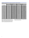
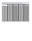
1. Slide the rear (short) adjustable link plate up (vertically)
inside the rear tube of the MRF-3D.
2. Align the lowest hole in the adjustable link plate with the
lower hole in the MRF-3D. Each hole in the adjustable
link corresponds with two degrees of vertical splay
angle.
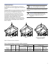
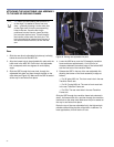
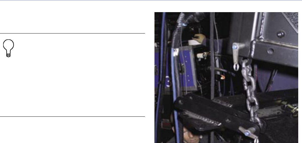
3. Slide the QRP through the lower hole, through the
adjustable link plate, and then through the hole on the
other side (see Figure 45). Make sure the QRP is seated
all the way in and locked into place.
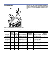
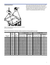
Figure 45. Pinning rear adjustable link plate
4. Lower the M3D array over the CQ assembly transition
frame and leave approximately 1 inch (25 mm) of
clearance between the bottom edge of the lowest M3D
and the front arm of the transition frame.
5. Release the QRP in the top of the rear adjustable link,
allowing the bottom of the chain assembly to align as
follows:
— For 30˚ splay MSL-4s: The front-most hole in the rear
Transition Frame arm
— For 22.5˚ splay MSL-4s: The next to front-most hole
in the rear Transition Frame arm
— For CQs: The rear-most hole in the rear Transition
Frame arm
Slide the QRP through the transition frame hole selected in
step 5, the lowest chain link, and then through the transition
frame hole on the other side. Make sure the pin is seated all
the way in and locked into place.
Repin the top of the rear adjustable link in the highest hole
possible without lifting the rear of the MSL-4 cabinets. For
most applications, this will be the 2˚ hole.


