


36
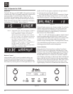
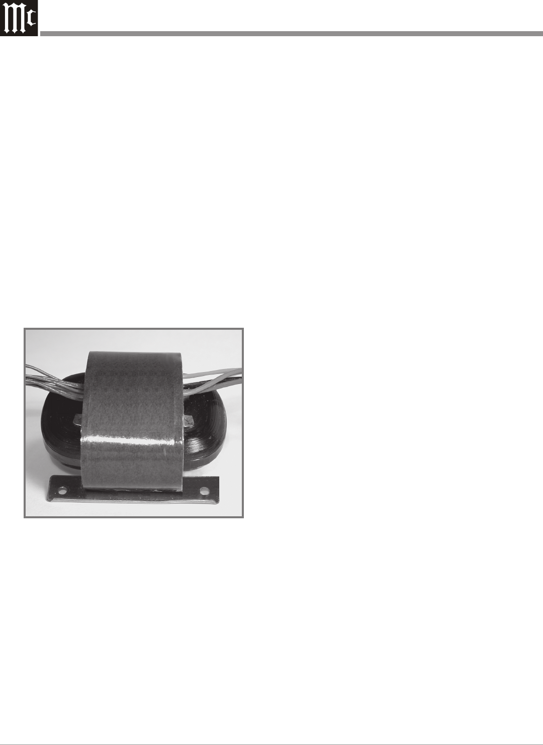
Figure 104
problems electrically. By developing electronic circuits the
meters are made to respond to short intervals with an accu-
racy of 95%! To permit the eye to see such high speed mo-
tion, the electronic circuits that drive the meter pointer are
time stretched. Special logarithmic circuitry allows the
meter to indicate a 60dB plus range, without resorting to a
Meter Range Switch.
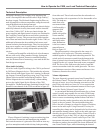
Power Supply Circuits
To compliment the design of the C500, there are two
indentical fully regulated power supplies, one for each chan-
nel. The C500 Contoller contains both low and high voltage
regulated power supplies for each channel. It also supplies
the appropriate voltages to meet the different requirements
of the C500 Preamplifier and C500 Tube Preamplifier. The
special “R” core transformers, one for each channel, supply
the necessary voltage/current for the low and high voltage
regulated circuitry and are housed in shielded enclosures.
Refer to figure 104.
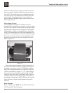
Most owners desire one power switch for the whole au-
dio system. The C500 Controller is equipped with circuits
providing remote Power Control On/Off signals to McIn-
tosh Source Components and Power Amplifiers. When the
C500C is switched On, a digital “1” (+5V) signal changes
the operational state of digital control circuitry and a DC
voltage is sent to the Power Control Main Jacks. There are
also special Power Control Jacks (Triggers and Passthru)
and together with options in SETUP allow for the customiz-
ing of the Power Control Control Signals In for specific
functions.
Block Diagrams
Refer to folded sheet “Mc2B” for the C500 Controller and
C500 Preamplifier Block Diagrams.
Technical Description, con’t