


13
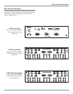
19. Connect Cables from the External Sound Processor Left
and Right Outputs to the C500 Preamplifier PROCES-
SOR FROM LEFT and RIGHT Input Jacks.
20. Connect Cables from the Music Server Left and Right
Outputs to the C500 Preamplifier Unbalanced SRVR
(4) LEFT and RIGHT INPUTS Jacks.
21. Connect Cables from the Music Server Left and Right
Inputs to the C500 Preamplifier Unbalanced SRVR (4)
LEFT and RIGHT OUTPUTS Jacks.
22. Connect XLR Cables from the C500 Preamplifier
MAIN LEFT and RIGHT Balanced OUTPUTS, to one
of the Balanced Inputs on the Left and Right McIntosh
Power Amplifiers.
Note: If the C500 is not part of a Multichannel Audio
System, proceed to step 25.
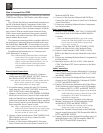
Passthru Connections:
The C500 Preamplifier has a special operating mode known
as Passthru, when it is used as part of a McIntosh Multi-
channel Sound System. The Front Left and Right Channels
coming from the McIntosh A/V Control Center connect to a
predetermined input at a preset volume level and then onto
the Left and Right Main Power Amplifiers/Loudspeakers.
Passthru requires several extra connections and activation
by using the SETUP Mode of the C500.
The following connection instructions, together with the In-
put and Output Connection Diagrams located on the sepa-
rate folded sheet “Mc1B”, are an example of a typical audio
system. Your system may vary from this, however the actual
components would be connected in a similar manner.
For additional information refer to “Connector and Cable
Information” on page 4.
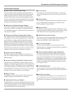
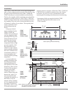
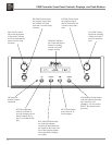
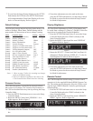
How to connect the C500
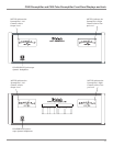
Figure A
23. Connect a Power Control Cable from the McIntosh A/V
Control Center Zone A Power Control Output Jack to
the C500C PASSTHRU Input Jack.
Note: The Passthru Mode will also work non-McIntosh
Multichannel Processors, the voltage required to
activate the Passthru feature is +5 to +12 Volts
D.C.
24. Connect XLR Cables from the McIntosh A/V Control
Center Zone A Outputs Front Left and Right to the
C500P CDR (5) LEFT and RIGHT INPUT Balanced
Connectors.
Note: Any of the C500C Inputs (except for the MM (8),
MC (9) and Record Link Inputs) both Balanced or
Unbalanced may be used for the Passthru Mode.
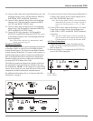
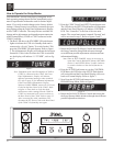
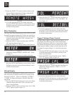
A.C. Power Connections:
25. Connect the supplied AC Power Cord between the
C500C AC Power Cord Socket and a live AC outlet.
Refer to figure B.
26. Proceed to page 23 for customizing the SETUP Fea-
tures of the C500 Preamplifier.
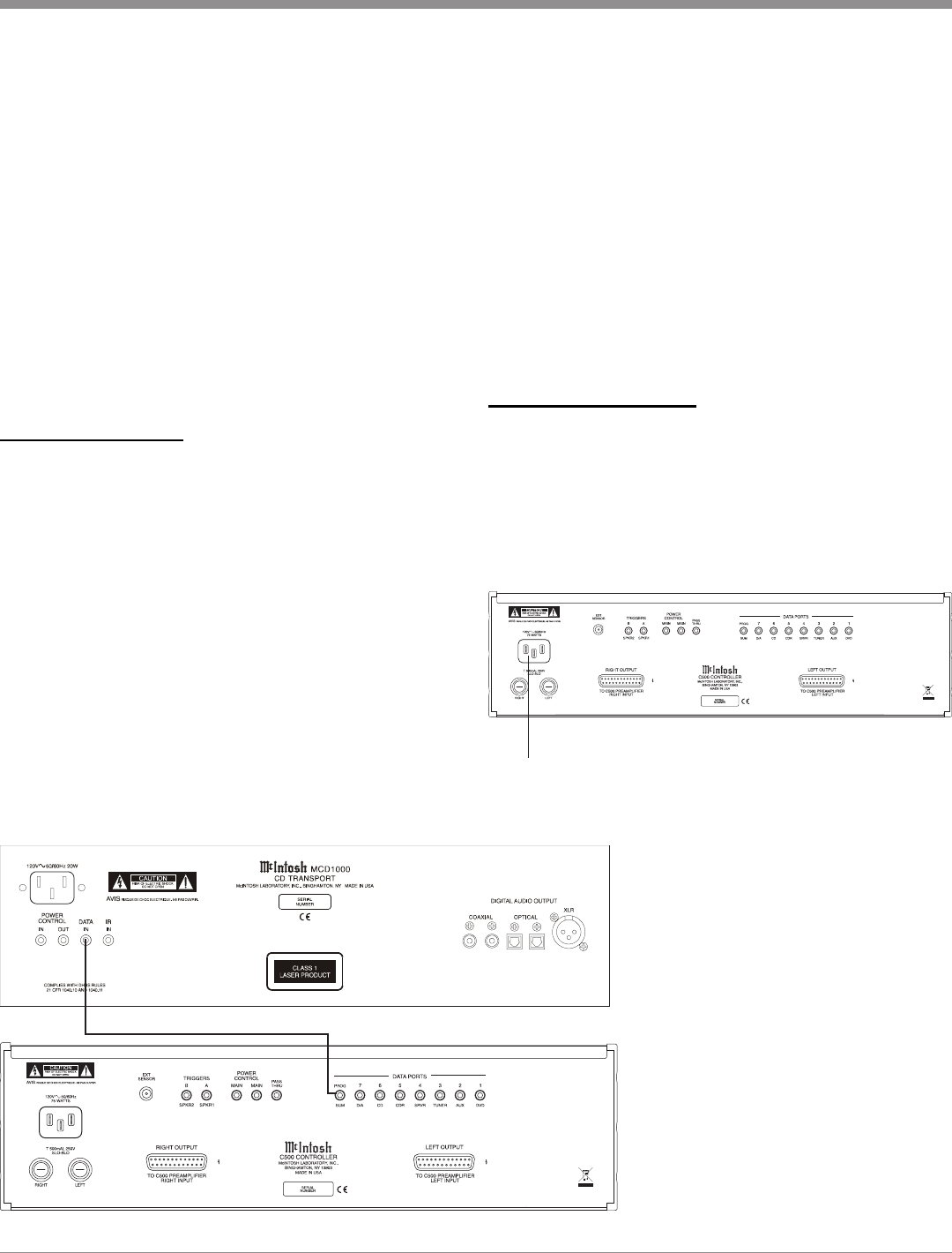
Connect to a
live AC Outlet
Figure B