16
Figure 6
2. Press the C500C Front Panel SETUP push-button once.
The LED above the SETUP Push-button will illuminate
and the Front Panel Display will indicate CONTROL-
LER. The “Controller” is the first of the two main
menus. The second main menu is named “Preamp” and
will be accessed in step 5. Refer to figures 2 and 5.
3. Rotate the BALANCE (Menu) Control and notice that
the Setup Controller Setup Mode advances through
seven different possible adjustment selections and one
informational display.
Note: When in SETUP MODE, it may be necessary to
rotate the Controls BALANCE (Menu), RECORD
(Select 1) and LISTEN (Select 2) either clockwise
or counter-clockwise to the desired function or
setting.
4. Press the SETUP Push-button to exit the CONTROL-
LER Menu, the LED above the SETUP Push-button
will extinguish and the Front Panel Display will revert
back to its normal display. Refer to figure 3.
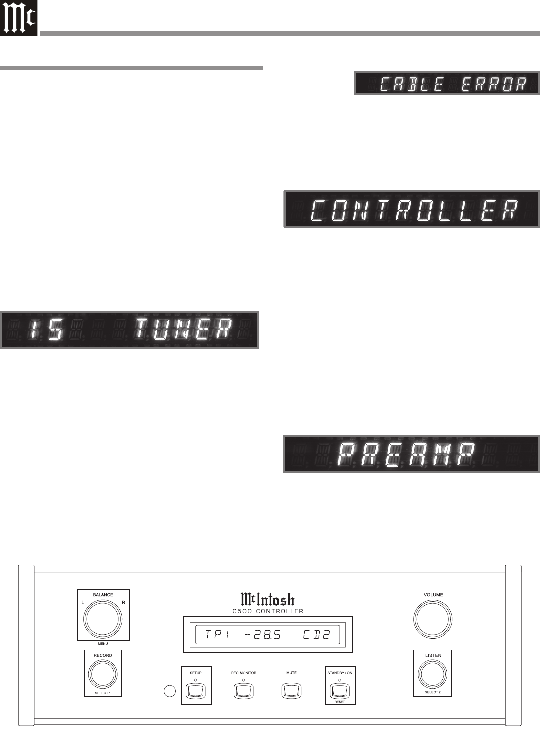
5. Now Press the SETUP Push-button twice to enter the
PREAMP Setup Menu. Refer to figure 6.
6. Rotate the BALANCE (Menu) Control and notice that
the Setup Preamp Mode advances through nine different
possible adjustment selections.
How to Operate the Setup Modes
Your McIntosh C500 has been factory configured for de-
fault operating settings that will allow immediately enjoy-
ment of superb audio without the need for further adjust-
ments. If you wish to make changes to the factory default
settings, a Setup Feature is provided to customize the oper-
ating settings using the Front Panel Alphanumeric Display
on the C500C Controller. The setup fuctions available for
change and/or adjustments are dependent upon connection
of the Preamplifier(s) C500P or C500T connected to the
C500C Controller.
1. The Red LED above the STANDBY/ON push-button
lights to indicate the C500 is in Standby mode and is
connected to a live AC Outlet. To switch On the C500,
press the STANDBY/ON push-button. Refer to figure
2. The Alphanumeric Display will indicate the last input
listened to. If this is the first time the C500 is switched
on, the display will indicate “15 TUNER”, refer to fig-
ure 3.
Note: Dependent upon which Preamplifier (C500P or
C500T) is connected to the C500C, the Front
Panel Alphanumeric Display will indicate
different operational messages when switched
On, refer to page 28 for additional information.
If the Front Panel Alphanumeric Display
indicates CABLE ERROR, remove the AC Power
Cord from the Rear Panel of the C500C. Refer
to figure 4. Then check to verify that both
interconnect cables coming from the C500P or
C500T are connected to the correct sockets on
the Rear Panel of the C500C. Refer to page 12.
After correcting the cable connection error,
reconnect the AC Power Cord to the Rear Panel
of the C500C. Perform Step one again.
Figure 3
Figure 5
Figure 4
Figure 2


