18
Meter Illumination
Figure 11
The Front Panel Meter Illumination of the C500P or C500T
Preamplifiers may be switched Off. Follow the steps below:
1. Press the SETUP Push-button once to access the Setup
Controller Mode unless the C500C is already in the
Setup Controller Mode.
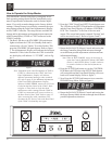
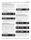
2. Rotate the MENU Control until the words “METER
ON” appears. Refer to figure 10.
3. Rotate the SELECT 2 Control until the Front Panel Al-
phanumeric Display indicates “METER OFF”. Refer
to figure 11.
4. If no other adjustements are to be made at this time,
press the SETUP Push-button to exit the Setup Control-
ler Mode or proceed to the next desired Setup Control-
ler Mode for adjustment.
Volume Display
The Front Panel Alphanumeric Display of the current vol-
ume setting may be indicated either as a Percentage of the
maximum volume (0 - 100%) or in Decibels (-92.0dB to
+15.0dB). To change the display to Decibels follow the
steps below:
1. Press the SETUP Push-button once to access the Setup
Controller Mode unless the C500C is already in the
Setup Controller Mode.
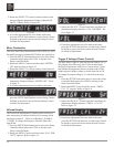
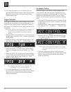
2. Rotate the MENU Control until the words “VOL PER-
CENT” appears. Refer to figure 12.
Figure 13
The Rear Panel Trigger A Jack can provide either a 5 or 12
Volt Output when activated, with 5 Volts as the default.
McIntosh Components with Power Control utilize 5 Volts;
non-McIntosh components when connected to the C500C
might required a higher voltage to switch them On or Off.
To change the output voltage to 12 volts follow the steps
below:
1. Press the SETUP Push-button once to access the Setup
Controller Mode unless the C500C is already in the
Setup Controller Mode.
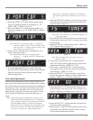
2. Rotate the MENU Control until the words “TRIGA
LVL 5V” appears. Refer to figure 14.
3. Rotate the SELECT 2 Control until the Front Panel Al-
phanumeric Display indicates “TRIGA LVL 12V”.
Refer to figure 15.
4. If no other adjustments are to be made at this time,
press the SETUP Push-button to exit the Setup Control-
ler Mode or proceed to the next desired Setup Control-
ler Mode for adjustment.
Trigger A Voltage (Power Control)
Figure 10
Figure 14
Figure 12
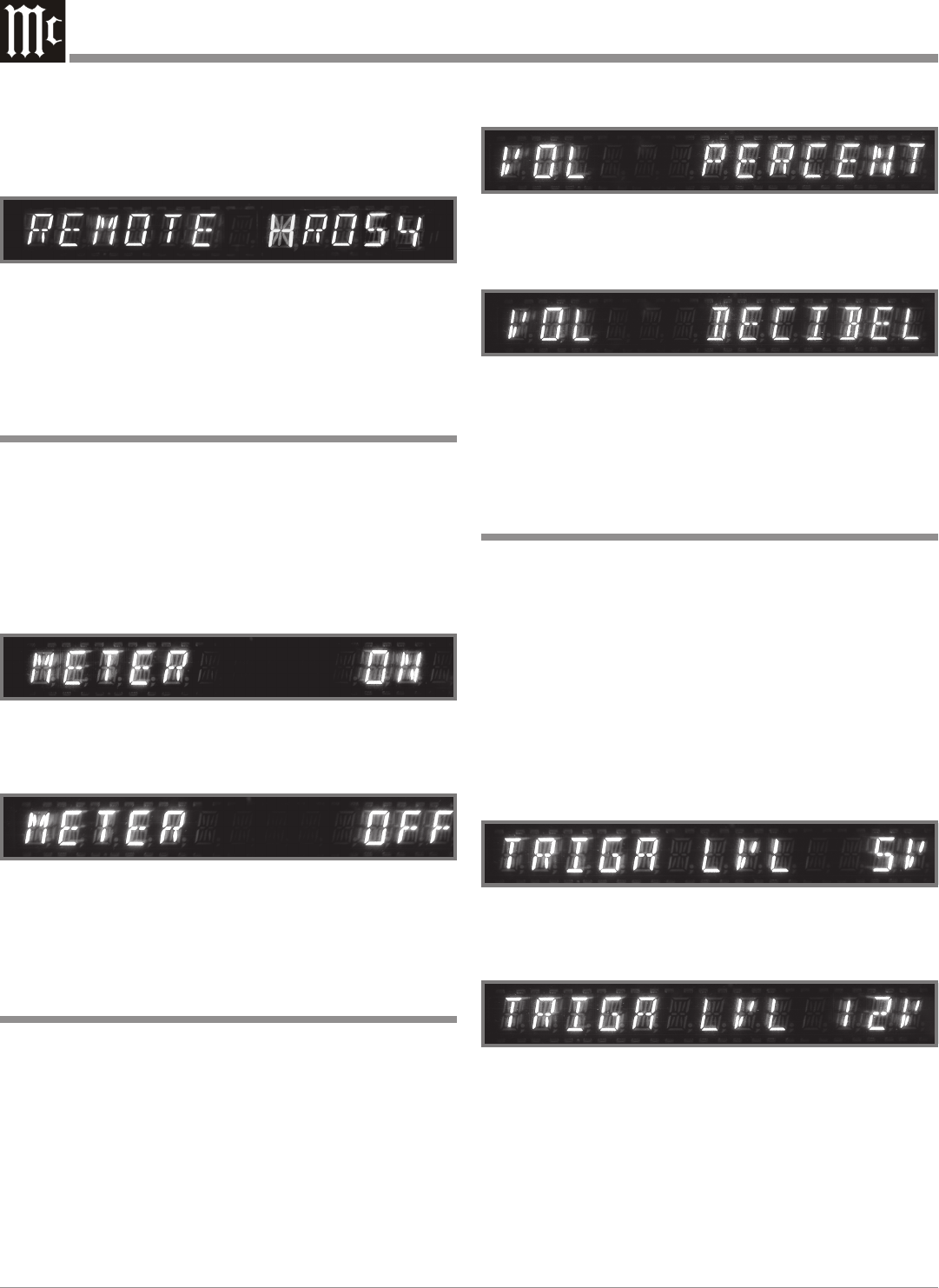
Figure 9B
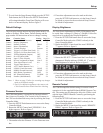
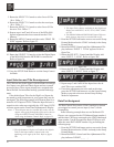
3. Rotate the SELECT 2 Control counterclockwise until
the Front Panel Alphanumeric Display indicates RE-
MOTE HR054. Refer to figure 9B.
4. If no other adjustments are to be made at this time,
press the SETUP Push-button to exit the Setup Control-
ler Mode or proceed to the next desired Setup Control-
ler Mode for adjustment.
3. Rotate the SELECT 2 Control until the Front Panel Al-
phanumeric Display indicates “VOL DECIBEL”. Re-
fer to figure 13.
4. If no other adjustments are to be made at this time,
press the SETUP Push-button to exit the Setup Control-
ler Mode or proceed to the next desired Setup Control-
ler Mode for adjustment.
Figure 15


