


12
This page contains information for connecting the McIntosh
C500C to the C500P or C500T and to other audio compo-
nents.
The C500 has the ability to automatically switch power
On/Off to McIntosh Source Components via the Power
Control Connections. The Data Port Connections allow for
the remote operation of basic functions using the C500 Re-
mote Control. With an external sensor connected to the
C500, remote control operation of the system is possible
from another room and/or when the C500 is located in a
cabinet with the doors closed.
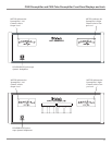
The connection instructions below, together with the In-
put and Output Connection Diagrams located on the sepa-
rate folded sheet “Mc3A/3B”, are an example of a typical
audio system. Your system may vary from this, however the
actual components would be connected in a similar manner.
For additional information refer to “Connector and
Cable Information” on page 4.
Note: Balanced and Unbalanced Inputs and Outputs
can be mixed. For example, you may connect
signal sources to Unbalanced Inputs and send
signals out from the Balanced Outputs. You can
also use Balanced and Unbalanced outputs
simultaneously, connected to different power
amplifiers.
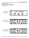
Power Control Connections:
1. Connect one of the supplied custom 23-Conductor
Cables from the C500C RIGHT OUTPUT Socket to
the C500P or C500T RIGHT INPUT Socket.
Note: After the cable connector is firmly seated into the
chassis socket, rotate the two locking screws on
either side until they are finger tight.
2. In a similar manner, connect the other 23-Conductor
Cable from the C500C LEFT OUTPUT Socket to the
LEFT INPUT Socket on the Preamplifier.
3. Connect a Cable from the C500C POWER CONTROL
MAIN Jack to the Power Control In Jack on the McIn-
tosh Left Channel Power Amplifier and another Control
Cable from the McIntosh Left Channel Power Amplifier
Power Control Out Jack to the McIntosh Right Channel
Power Amplifier Power Control In Jack.
Note: There is approximately a one-half second delay
added to the Power Control Out Jack signal going
to the next McIntosh Power Amplifier, to reduce
the strain on the AC Power Line.
4. Connect a Cable from the other C500C POWER CON-
TROL MAIN Jack to the Power Control In of the
McIntosh D/A Converter.
5. Connect a Cable from the McIntosh D/A Converter
Power Control Out Jack to the Power Control In of a
McIntosh AM/FM Tuner.
6. Connect a Cable from the McIntosh AM/FM Tuner
Control Out Jack to the Power Control In of a McIntosh
Audio/Video Player.
7. Connect any remaining McIntosh Source Components
in a similar manner.
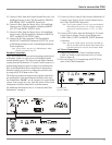
Data Control Connections:
8. Connect a Cable from the C500C D/A (7) DATA PORT
to the Data In Jack of the McIntosh MDA1000 D/A
Converter.
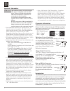
Note: If a McIntosh MCD1000 is part of the system,
connect the SUM DATA PORT Jack to the Data
Port In Jack on the MCD1000, using a Data
Cable. Refer to figure A.
9. Connect a Cable from the C500C TUNER (3) DATA
PORT to the Data In Jack of the McIntosh Tuner.
10. Connect a Cable from the C500C DVD (1) DATA
PORT to the Data In Jack of the McIntosh Audio/Video
Player.
11. Connect any remaining McIntosh Source Components in
a similar manner.
12. Optionally connect a RG-59 or RG-6 Cable from the
C500C Rear Panel EXT Sensor connector to the McIn-
tosh Sensor.
Audio Connections:
13. Connect XLR Cables from the McIntosh D/A Converter
to the C500 Preamplifier Balanced XLR D/A (7) LEFT
and RIGHT INPUTS.
14. Connect Cables from the McIntosh Tuner Fixed Audio
Outputs to the C500 Preamplifier Unbalanced TUNER
(3) LEFT and RIGHT INPUTS.
15. Connect Cables from the McIntosh Audio/Video Player
2CH Unbalanced Audio Outputs to the C500 Preampli-
fier Unbalanced DVD (1) LEFT and RIGHT INPUTS.
Note: The 2CH Balanced Audio Outputs of the McIntosh
Audio/Video Player may be connected to the C500
Preamplifier CD (6) INPUTS instead of the
Unbalanced Connections.
16. Connect Cables from the Turntable (with a Moving
Magnet Cartridge) to the C500 Preamplifier Unbal-
anced MM (8) LEFT and RIGHT INPUTS.
Note: If the Turntable has a Moving Coil Cartridge,
connect the cables to the MC (9) Inputs.
17. Connect the Turntable Ground Cable to the GND bind-
ing post located between the C500 Preamplifier MM (8)
LEFT and RIGHT INPUTS.
18. Connect Cables from the External Sound Processor Left
and Right Inputs to the C500 Preamplifier PROCES-
SOR TO LEFT and RIGHT Output Jacks.
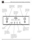
How to connect the C500