


7
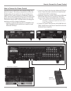
Installation
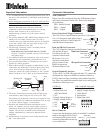
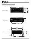
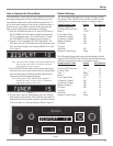
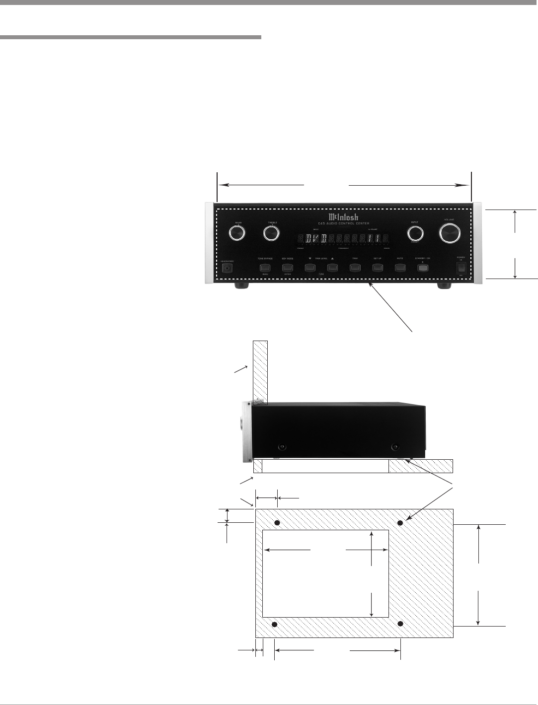
The C45 can be placed upright on a table or shelf, standing
on its four feet. It also can be custom installed in a piece of
furniture or cabinet of your choice. The four feet may be
removed from the bottom of the C45 when it is custom in-
stalled as outlined below. The four feet together with the
mounting screws should be retained for possible future use
if the C45 is removed from the custom installation and used
free standing. The required panel cutout, ventilation cutout
and unit dimen-
sions are
shown.
Always pro-
vide adequate
ventilation for
your C45. Cool
operation en-
sures the long-
est possible op-
erating life for
any electronic
instrument. Do
not install the
C45 directly
above a heat
generating com-
ponent such as
a high powered
amplifier. If all
the components
are installed in
a single cabinet,
a quiet running
ventilation fan
can be a defi-
nite asset in
maintaining all
the system com-
ponents at the
coolest possible
operating tem-
perature.
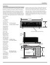
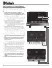
A custom
cabinet installa-
tion should pro-
vide the follow-
ing minimum
spacing dimen-
sions for cool
Installation
4-
7/8
"
12.38cm
17-
1/16
"
43.34cm
Cutout Opening for Custom Mounting
C45 Front Panel
Custom Cabinet Cutout
11
-1/2
"
29.21cm
14"
35.56cm
15-
1/16
"
38.26cm
1"
2.54cm
Cutout Opening
for Ventilation
Cutout Opening for Ventilation
Support
Shelf
Cabinet
Front
Panel
Chassis
Spacers
C45 Side View
in Custom Cabinet
C45 Bottom View
in Custom Cabinet
2"
5.08cm
10
-5/8
"
26.99cm
3/4
"
1.91cm
operation. Allow at least 2 inches (5.08cm) above the top, 2
inches (5.08cm) below the bottom and 1 inch (2.54cm) on
each side of the Audio Control Center, so that airflow is not
obstructed. Allow 17 inches (43.18cm) depth behind the
front panel. Allow 1-1/8 inch (2.9cm) in front of the mount-
ing panel for knob clearance. Be sure to cut out a ventila-
tion hole in the mounting shelf according to the dimensions
in the drawing.