


4
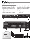
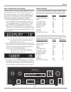
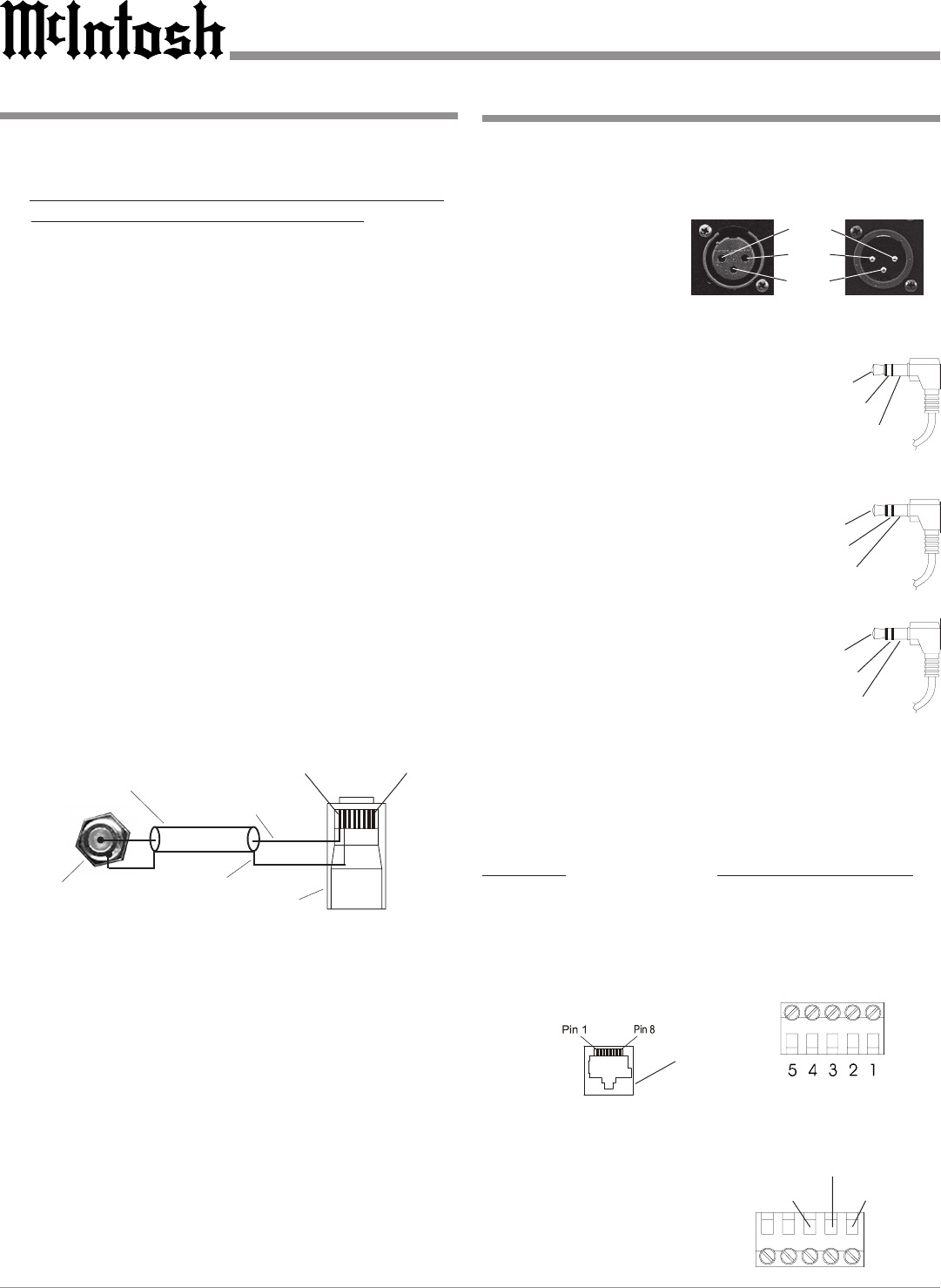
XLR Connectors
Below is the Pin configuration for the XLR Balanced Input
and Output Connectors on the C45. Refer to the diagram
for connection:
PIN 1: Shield/Ground
PIN 2: + Signal
PIN 3: - Signal
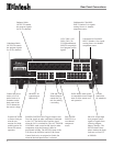
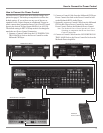
Power Control and Trigger Connectors
The C45’s Power Control Outputs provide a 5 volt signal.
Use a 1/8 inch stereo mini phone plug to
connect to the Power Control Input on
other McIntosh Components.
Data and IR Port Connectors
The C45’s Data Port Output provides Remote Control Sig-
nals and the IR Input
Port allows for the con-
nection of other brands
IR Sensors. Use a 1/8
inch stereo mini phone
plug to connect to the
Data Port Inputs on
McIntosh Source Units.
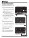
Keypad Terminal Connector
To use a WK-3 or WK-4 Keypad with the C45, connect the
shield and four leads of a shielded 4 conductor cable to a
RJ-45 Connector Plug, according to the numbers listed be-
low. There is a numbered connector built-in to each Keypad,
which has a different pin out.
C45 RJ-45 WK-3 and WK-4 Keypad
1. Signal Data 1. Supply Voltage Positive
2. Signal Data Gnd. 2. Supply Voltage Negative
and Cable Shield 3. Cable Shield
3. N/C 4. Signal Data
4. Supply Voltage Negative 5. Signal Data Gnd
5. Supply Voltage Positive
6. N/C
7. N/C
8. N/C
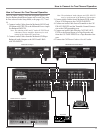
RAA1 Connector
Connect the shield and two leads of a shielded 2 conductor
cable to the supplied 5 Pin Termi-
nal Connector Plug. Refer to the
connection information on the top
cover of the RAA1.
Connector Information
Pin 1
Pin 2
Pin 3
Important Information
1. It is recommended that a qualified professional assist you in
the choice and installation of a McIntosh Audio System for
your home.
2. Before making any connections to the C45, make sure that
the Main POWER Switch is in the Off position. When the
C45 and other McIntosh Components are in their Standby
Mode the Microprocessor’s Circuitry inside each
component is active and communication is occurring
between them. Failure to do so could result in
malfunctioning of some or all of the system’s normal
operations.
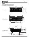
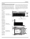
3. The optional McIntosh TM1 AM/FM Tuner Module can be
added to the C45 Audio Control Center. The TM1 is
available from your McIntosh Dealer and can be installed
at any time, usually while you wait. Refer to page 27 for
additional information on the TM1.
4. The following Connecting Cable is available from the
McIntosh Parts Department:
Data and Power Control Cable Part No. 170-202
Six foot, 2 conductor shielded, with two 1/8 inch stereo
mini phone plugs.
5. For additional connection information, refer to the owner’s
manual(s) for any component(s) connected to the C45.
6. Up to four McIntosh Sensors or Keypads can be wired in
parallel for remote operation.
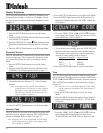
7. When a McIntosh WK-2 Keypad or a R649 Sensor is to be
connected to the McIntosh C45 Audio Control Center that
uses a RJ-45 Connector Plug instead of the “F” Coax
Connector, connect the Center Conductor to Pin 1 and the
Shield Conductor to Pin 2. Refer to the illustration below.
8. The Power Control Signal present at the ACC(B) Jack is
controllable by either using the ACC ON or ACC OFF
Push-buttons on the Remote Control or by assignment when
in the Setup Mode. For additional information refer to page
19 “Power Control Triggers” in this manual.
9. Balanced and Unbalanced Inputs and Outputs can be
mixed. For example, you may connect signal sources to
Unbalanced Inputs and send signals from the Balanced
Outputs. You can also use Balanced and Unbalanced
Outputs simultaneously, connected to different Power
Amplifiers.
10. Sound Intensity is measured in units called Decibels and
“dB” is the abbreviation.
RJ-45
Plug
Data Ground
(to Pin 2)
Shielded Cable Data Signal
(to Pin 1)
“F” Connector
Pin 8
Pin 1
Positive
N/C
Ground
IR Input Port Connector
Data Signal
Ground
N/C
Data Signal
N/C
Data Ground
Data Port Connector
C45
Keypad
Socket
Red (TV)
Black (RF)
Green (GND)