


13
ENGLISH
BASIC
CONNECTIONS
BASIC OPERATION
ADVANCED
CONNECTIONS
SETUP
ADVANCED
OPERATION
TROUBLESHOOTING
OTHERS
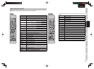
NAMES AND
FUNCTIONS
BASIC
CONNECTIONS
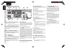
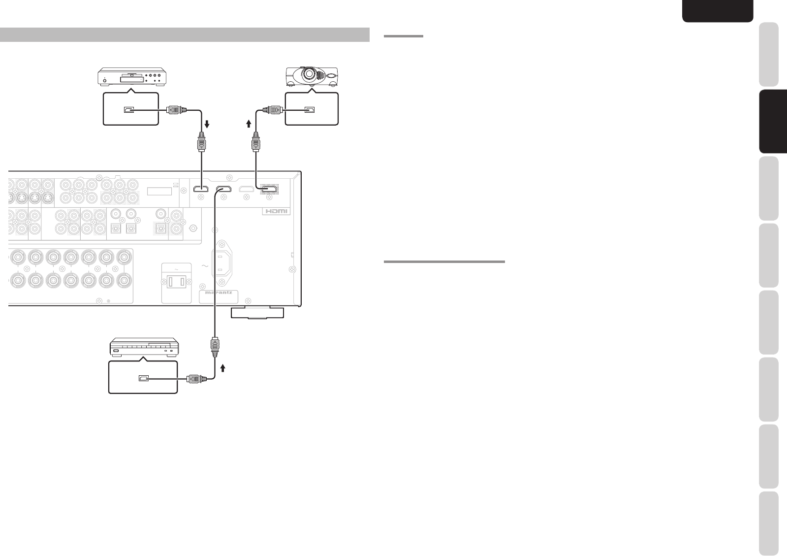
HDMI JACK
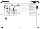
This unit has 3 HDMI inputs and one HDMI output. It
can send digital video and audio signals from DVDs and
other sources directly to a display. It minimizes signal
degradation caused by analog conversion so that high
quality images can be enjoyed.
Select an input source from the OSD menu system.
(See page 21)
Notes:
• When the HDMI output is connected to a display
monitor that does not support HDCP*, signals are
not output. To view images in HDMI, it is necessary
to connect to a display that supports HDCP*.
• There may be no image output if connected to a
TV or display that is not compatible with the above
format.
• Refer to the instruction manual of the TV or display
to be connected to the unit for detailed information
regarding the HDMI terminal.
* HDCP: High-bandwidth Digital Content Protection
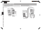
CONNECTING HDMI COMPONENTS
An HDMI cable (sold separately) is used to connect
the HDMI jack on the unit with the HDMI jack on a DVD
player, TV, projector or other component. To transmit
multichannel audio via HDMI, the connected player
must support multichannel audio transmission through
its HDMI jack.
HDMI video streaming is compatible with DVI in
principle. Therefore, it is possible to connect to a TV
or monitor that has a DVI terminal using an HDMI-DVI
conversion cable or plug. When connecting to a DVI
terminal, connect the audio signal separately.
Notes:
• Some HDMI components can be controlled over
the HDMI cable, but this unit cannot control other
components this way.
• When connected to a monitor (i.e., TV, projector,
etc.) that does not support HDCP, video and audio
are not output.
• DVI cables come with 24-pin and 29-pin plugs. This
unit supports 24-pin DVI-D cables; 29-pin DVI
cables cannot connect to it.
• Some source devices such as DVD players does not
support HDMI repeater like those of the unit. In such
case, pictures are not properly projected on monitors
such as TVs and projectors.
• When multiple components are connected to this
unit, turn power to unused components off to
prevent interference between them.
• Disconnecting or connecting cables with the power
on can damage the equipment. Turn the power off
before disconnecting or connecting cables.
• Some DVD-Audio disks disable downmixing.
These types of disks are not played back correctly
unless the left, center, right and surround left and
right speakers, and subwoofer are connected.
• If a DVD player that does not support HDMI 1.1 is
connected to the unit, multi channel PCM playback
is not possible even with DVD-Audio disks.
•
If a DVD player or other device with DVI output is
connected to the unit, a separate audio cable (optical-
digital, coaxial digital or analog) is needed for the
audio signals. In this case, select the connected audio
input as explained in “1 INPUT SETUP”. (See page
21)
• Multi channel PCM signals and audio signals of 64
kHz or higher that are input from the HDMI jack are
not output from the DIGITAL OUT jacks.
• Depending on the quiality of the cable used, the
HDMI signal may be affected by noise.
• Audio units that use sampling frequencies of 128
kHz and above are not supported.
• When only HDMI components are connected, OSD
will not be displayed. (See page 20)
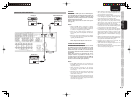
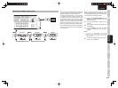
DVD player VIDEO PROJECTOR
R SR
C
SW SBR
SL SBLL
R
R
SPEAKER SYSTEMS : 6-8 OHMS
SPEAKER SYSTEMS : 6-8 OHMS
R
R
L
L
L
L
L
L
R
R
IN
IN
OPT
OPT
DIGITAL OUT
DIGITAL OUT
L SL C SBL
R SR SW SBR
R
L
FM
(
75Ω
)
GND AM
C
C
R
R
/
/
P
P
R
R
C
C
B
B
/
/
P
P
B
B
Y
Y
ANTENNA
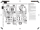
DIGITAL IN
DIGITAL IN
OUT
OUT
IN
IN
CD/CDR
CD/CDR
OUT
OUT
IN
IN
TAP E
TAPE
VCR
VCRDVDTV
AUDIO
AUDIO
DSS
DSS
NIN
OUT
OUT
C
C
R
R
/
/
P
P
R
R
C
C
B
B
/
/
P
P
B
B
Y
Y
DSS
DSSTV DVD R
IN
VCR IN
VCR OUT
VCR OUT
MONITOR OUT
MONITOR OUT
INPUT
INPUT
1
1
INPUT
INPUT
2
2
S-VIDEO
VIDEO
PRE OUT
CENTER
CENTER
FRONT
FRONT
SURROUND BACK
SURROUND BACK
S. SPEAKER B
S. SPEAKER B
SURROUND
SURROUND
AC IN
AC IN
MONITOR
MONITOR
OUT
OUT
INPUT
INPUT
3
3
COMPONENT
COMPONENT
VIDEO
VIDEO
OUT
OUT
REMOTE CONT.
REMOTE CONT.
2
2
1
1
4
4
3
3
7.1CH INPUT
(
AUX 2
)
AC OUTLETS
AC OUTLETS
120V 60Hz
120V 60Hz
SWITCHED
SWITCHED
1.25A 150W
1.25A 150W
MODEL NO. SR4003
MODEL NO. SR4003
INPUT 3
INPUT 3
OUTPUT
OUTPUT
INPUT 2
INPUT 2
INPUT 1
INPUT 1
IN
IN
FLASHER
FLASHER
OUTPUT
OUTPUT
INPUT 2
INPUT 2
INPUT 1
INPUT 1
HDMI OUTPUT
HDMI INPUT
HDMI OUTPUT
Satellite Tuner
CONNECTING HDMI COMPONENTS