


14
ENGLISH
BASIC
CONNECTIONS
BASIC OPERATION
ADVANCED
CONNECTIONS
SETUP
ADVANCED
OPERATION
TROUBLESHOOTING
OTHERS
NAMES AND
FUNCTIONS
BASIC
CONNECTIONS
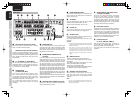
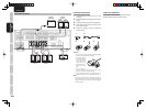
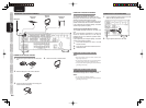
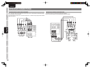
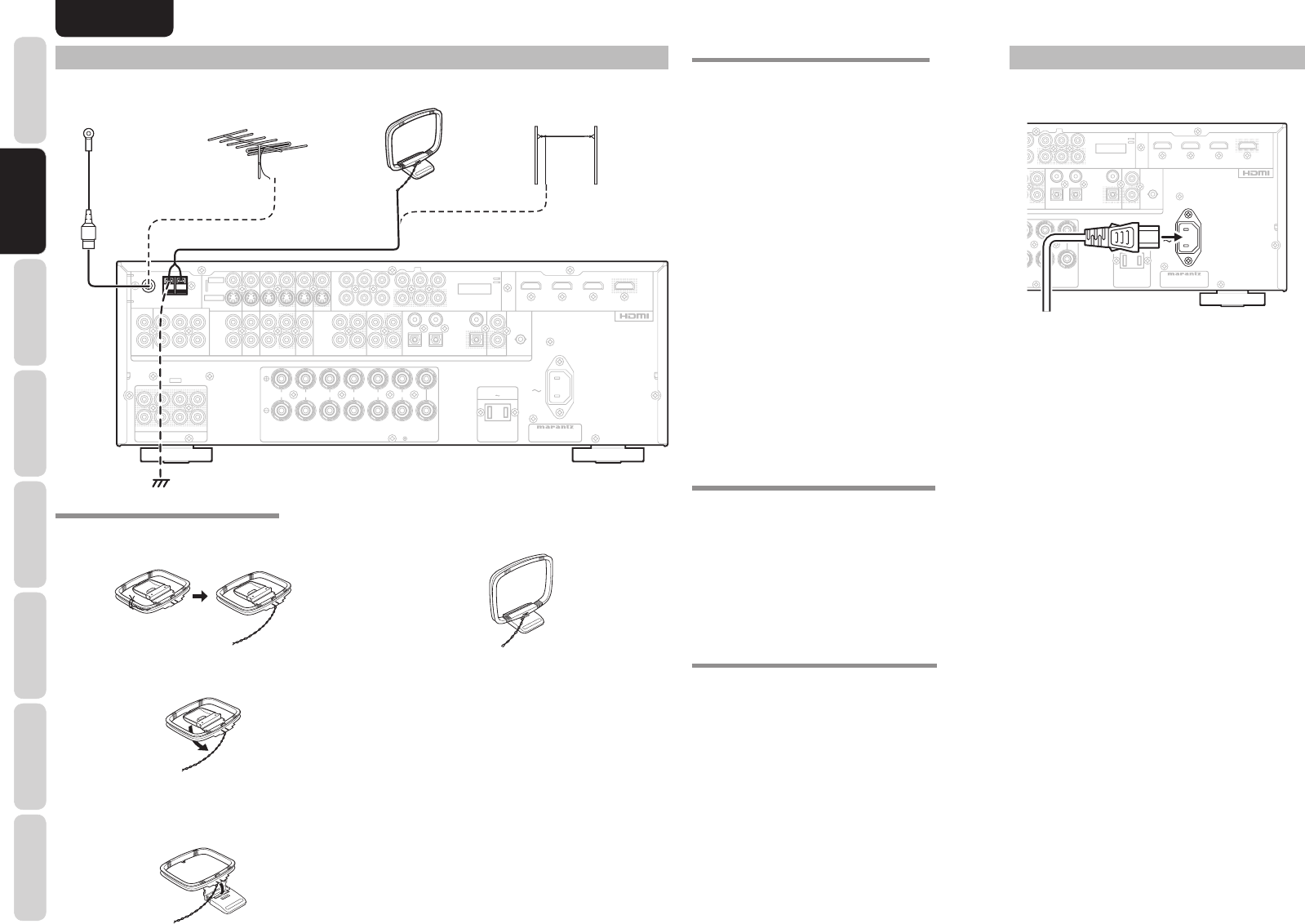
CONNECTING THE ANTENNA TERMINALS
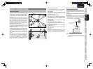
ASSEMBLING THE AM LOOP ANTENNA
1. Release the vinyl tie and take out the connection
line.
2. Bend the base part in the reverse direction.
3. Insert the hook at the bottom of the loop part
into the slot at the base part.
CONNECTING THE SUPPLIED ANTENNAS
Connecting the supplied FM antenna
The supplied FM antenna is for indoor use only.
During use, extend the antenna and move it in various
directions until the clearest signal is received.
Fix it with push pins or similar implements in the
position that will cause the least amount of distortion.
If you experience poor reception quality, an outdoor
antenna may improve the quality.
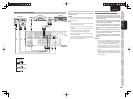
Connecting the supplied AM loop antenna
The supplied AM loop antenna is for indoor use
only.
Set it in the direction and position it to where you
receive the clearest sound. Put it as far away as
possible from the unit, televisions, speaker cables,
and power cords.
If you experience poor reception quality, an outdoor
antenna may improve the quality.
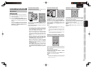
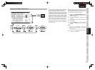
1.
Press and hold down the lever of the AM
antenna terminal.
2.
Insert the bare wire into the antenna terminal.
3.
Release the lever.
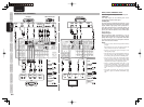
CONNECTING AN FM OUTDOOR ANTENNA
Notes:
• Keep the antenna away from noise sources (neon
signs, busy roads, etc.).
• Do not put the antenna close to power lines. Keep it
well away from power lines, transformers, etc.
• To avoid the risk of lightning and electrical shock,
grounding is necessary.
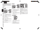
CONNECTING AN AM OUTDOOR ANTENNA
An outdoor antenna will be more effective if it is
stretched horizontally above a window or outside.
Notes:
• Do not remove the AM loop antenna.
• To avoid the risk of lightning and electrical shock,
grounding is necessary.
4. Place the antenna on stable surface.
R
R
SR
SR
C
C
SW
SW
SBR
SBR
SL
SL
SBL
SBL
L
L
R
R
SPEAKER SYSTEMS : 6-8 OHMS
SPEAKER SYSTEMS : 6-8 OHMS
R
R
L
L
L
L
L
L
R
R
IN
IN
OPT
OPT
DIGITAL OUT
DIGITAL OUT
L
L
SL
SL
C
C
SBL
SBL
R
R
SR
SR
SW
SW
SBR
SBR
R
R
L
L
FM
FM
(
(
75
75
Ω
Ω
)
)
GND
GND
AM
AM
C
C
R
R
/
/
P
P
R
R
C
C
B
B
/
/
P
P
B
B
Y
Y
ANTENNA
ANTENNA
DIGITAL IN
DIGITAL IN
OUT
OUT
IN
IN
CD/CDR
CD/CDR
OUT
OUT
IN
IN
TAPE
TAPE
VCR
VCR
DVD
DVD
TV
TV
AUDIO
AUDIO
DSS
DSS
IN
IN
OUT
OUT
C
C
R
R
/
/
P
P
R
R
C
C
B
B
/
/
P
P
B
B
Y
Y
DSS
DSS
TV
TV
DVD
DVD
VCR IN
VCR IN
VCR OUT
VCR OUT
MONITOR OUT
MONITOR OUT
INPUT
INPUT
1
1
INPUT
INPUT
2
2
S-VIDEO
S-VIDEO
VIDEO
VIDEO
PRE OUT
PRE OUT
CENTER
CENTER
FRONT
FRONT
SURROUND BACK
SURROUND BACK
S. SPEAKER B
S. SPEAKER B
SURROUND
SURROUND
AC IN
AC IN
MONITOR
MONITOR
OUT
OUT
INPUT
INPUT
3
3
COMPONENT
COMPONENT
VIDEO
VIDEO
OUT
OUT
REMOTE CONT.
REMOTE CONT.
2
2
1
1
4
4
3
3
7.1CH INPUT
7.1CH INPUT
(
(
AUX 2
AUX 2
)
)
AC OUTLETS
AC OUTLETS
120V 60Hz
120V 60Hz
SWITCHED
SWITCHED
1.25A 150W
1.25A 150W
MODEL NO. SR4003
MODEL NO. SR4003
INPUT 3
INPUT 3
OUTPUT
OUTPUT
INPUT 2
INPUT 2
INPUT 1
INPUT 1
IN
IN
FLASHER
FLASHER
FM
FM
(
(
75
75
Ω
Ω
)
)
GND
GND
AM
AM
ANTENNA
ANTENNA
AM Loop
Antenna
AM External
Antenna
FM External
Antenna
FM Antenna
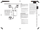
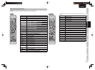
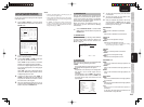
CONNECTING THE AC POWER CABLE
1.
Plug the supplied AC power cable to the AC IN
socket on the rear panel of the unit.
R SR
C
SW SBR
SL SBLL
R
MS
SPEAKER SYSTEMS : 6-8 OHMS
RL
L
LLR
IN
IN
OPT
OPT
DIGITAL OUT
DIGITAL OUT
L SL C SBL
R SR SW SBR
R
L
FM
(
75Ω
)
GND AM
C
C
R
R
/
/
P
P
R
R
C
C
B
B
/
/
P
P
B
B
Y
Y
ANTENNA
DIGITAL IN
DIGITAL IN
OUT
OUTIN
D
/CDR
CD/CDR
OUTIN
TAPEVCRDVDTV
AUDIO
DSS
IN OUT
C
R
//
P
P
R
R
C
B
/P
B
YDSSTV DVD VCR IN VCR OUT
MONITOR OUT
INPUT
1
INPUT
2
S-VIDEO
VIDEO
PRE OUT
CENTER
CENTERFRONT SURROUND BACK
S. SPEAKER B
U
RROUND
SURROUND
AC IN
AC IN
MONITOR
MONITOR
OUT
OUT
INPUT
INPUT
3
3
COMPONENT
COMPONENT
VIDEO
VIDEO
OUT
OUT
REMOTE CONT.
REMOTE CONT.
2
2
1
1
4
4
3
3
7.1CH INPUT
(
AUX 2
)
AC OUTLETS
AC OUTLETS
120V 60Hz
120V 60Hz
SWITCHED
SWITCHED
1.25A 150W
1.25A 150W
MODEL NO. SR4003
MODEL NO. SR4003
INPUT 3
INPUT 3
OUTPUT
OUTPUT
INPUT 2
INPUT 2
INPUT 1
INPUT 1
IN
IN
FLASHER
FLASHER
AC IN
AC IN
2.
Plug the power cable into an AC outlet.