


Lowrance - LVR-250 Installation and Operation Instructions6
Installation
This Lowrance radio is designed to generate a digital maritime distress call to facilitate search
and rescue. To be effective as a safety device, this radio must be used only within the geo-
graphic range of a shore-based VHF marine Channel 70 distress and safety watch system. The
geographic range may vary but under normal conditions is approximately 20 nautical miles.
Installation Options
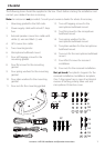
There are two ways to install the radio. You can choose:
A deck or overhead mounted gimbal installation• . The reversible mounting gimbal is fixed
to a suitable site and the radio is placed into it. The radio can be removed for storage and
the viewing angle can be adjusted.
A• recessed installation. The radio is recessed into a cavity cut into a bulkhead. The radio
fixture is permanent and the viewing angle cannot be adjusted.
Location Requirements
Please check these before doing any cutting or drilling.
Whichever installation method you choose, ensure that the chosen location:
Is at least 3’ (1 m) from the antenna•
Allows easy connection to (at least) a 10 Amp fused 13.6 V DC electrical source and the •
antenna
Is at least 1.5’ (45 cms) from the compass to avoid creating magnetic deviation of the •
compass during radio operation
Has a suitable space close by for installing the microphone bulkhead mount•
Provides easy access to the controls on the front panel •
Provides reasonable access to the wiring at the •
back of the radio
Provides enough room to fix the DSC warning •
label
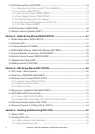
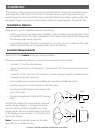
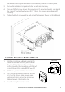
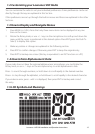
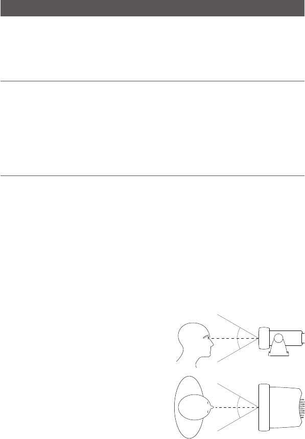
The VHF has a large LCD screen with an optimum
viewing angle of approx. +/-20 deg. Ensure the
chosen location provides a suitable view of the
display. Ideally, the user should be directly in front
of the display or no more than +/-20 deg from the
front of the display.
Note: If unsure, temporarily power up the radio
and check for a suitable location.
20˚
20˚
20˚
20˚
Side
Top